
A fully automatic rotary positioning welding device between guardrail components

A positioning welding, fully automatic technology, applied in welding equipment, auxiliary devices, auxiliary welding equipment, etc., can solve problems such as hidden safety hazards and low efficiency, and achieve the effect of high welding efficiency, high welding flexibility, and full automation.

Active Publication Date: 2018-07-03
广东固朗新型材料有限公司
View PDF6 Cites 0 Cited by
  • Summary
  • Abstract
  • Description
  • Claims
  • Application Information

AI Technical Summary

Problems solved by technology

[0002] The existing spliced ​​guardrail is connected and fixed by splicing as a whole, thus avoiding the adverse effects caused by welding. However, welding is generally used at the position where the vertical beam and the base are connected. Because this position is the main bearing point, the welding connection is relatively stronger. However, the traditional welding method is done by manual welding, which is very inefficient and has potential safety hazards. In order to improve the welding efficiency between the vertical beam and the base, It is necessary to make further improvements to the existing welded structure

Method used


Image

  • A fully automatic rotary positioning welding device between guardrail components
  • A fully automatic rotary positioning welding device between guardrail components
  • A fully automatic rotary positioning welding device between guardrail components

Examples


Embodiment 1

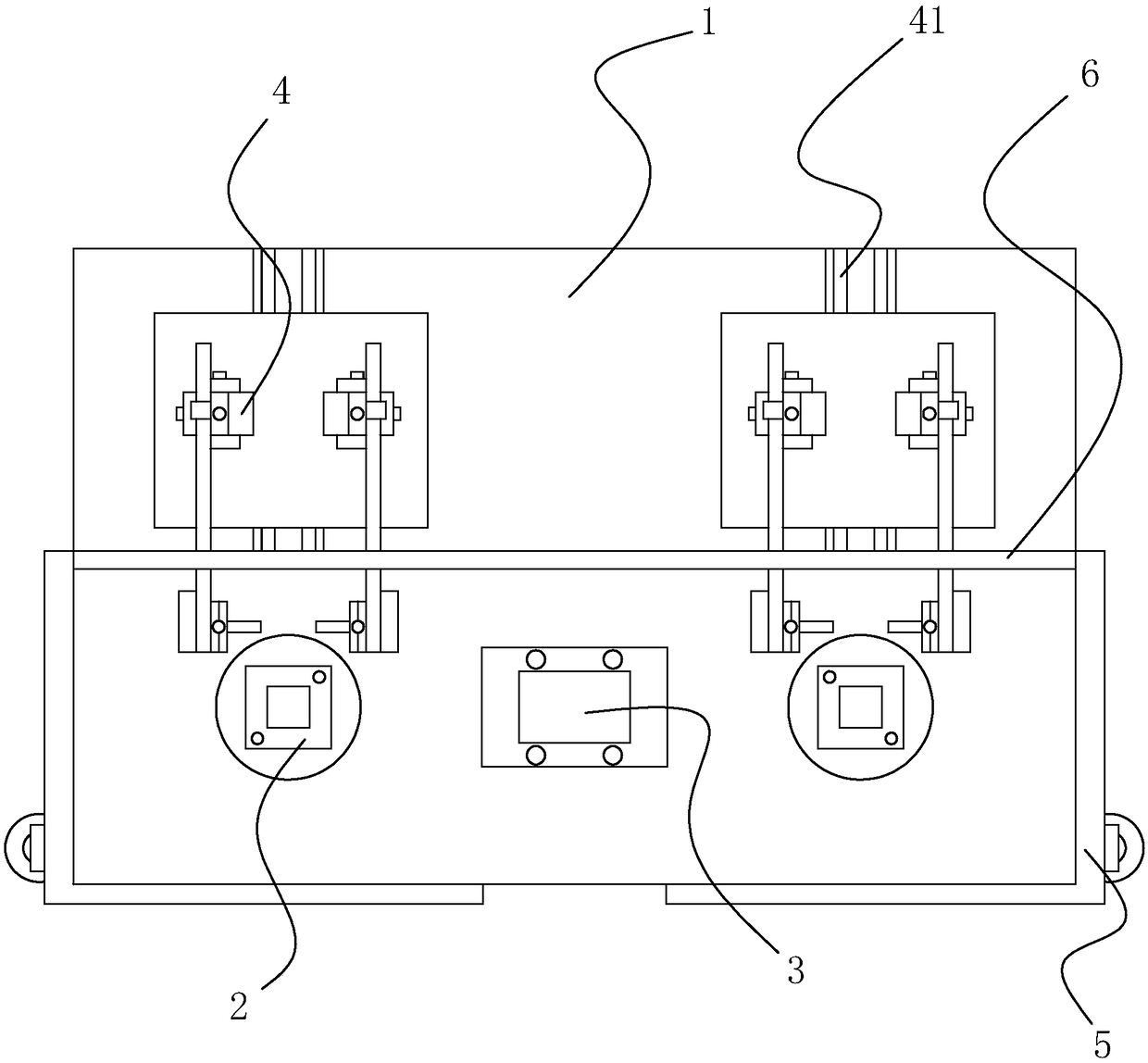
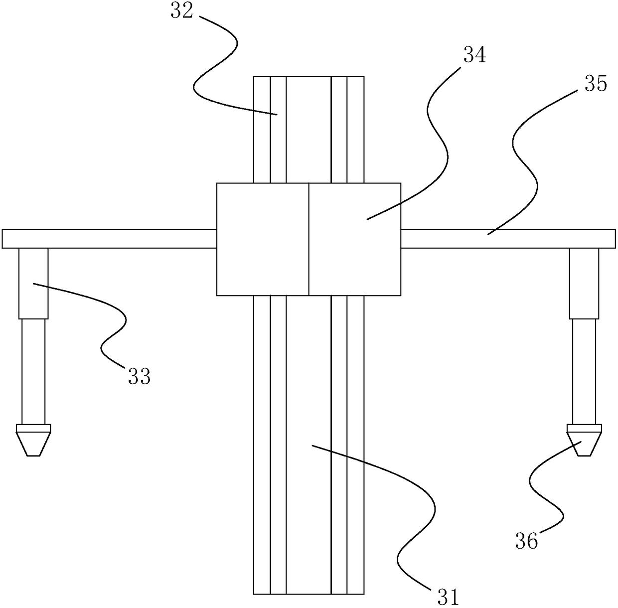
[0018] Such as Figure 1-Figure 5 As shown, a fully automatic rotary positioning welding device between guardrail components includes a workbench 1 for placing vertical beams and bases. The first positioning assembly 2 for fixing the base and the first positioning assembly 2 for fixing the vertical beams are arranged on the workbench 1. Two positioning components 3 , welding components 4 and protection components 5 . Before welding, the vertical beam and the base are set up and down, the base is fixed on the first positioning assembly 2, the lower end of the vertical beam is connected to the base, the position where the vertical beam and the base are connected is the welding position, and the upper end of the vertical beam is fixed by the second positioning assembly 3, The welding assembly 4 is used to weld the welding position, and the protective assembly 5 is used to prevent sparks from flying around during the welding process and block the strong light during welding.

Embodiment 2

[0020] A fully automatic rotary positioning welding device between guardrail components, including a workbench 1 for placing a vertical beam and a base, and a first positioning assembly 2 for fixing the base and a second positioning assembly for fixing the vertical beam are arranged on the workbench 1 3. Welding component 4 and protective component 5 . The welding device also includes a first transport assembly for transporting the base and a second transport assembly for transporting the vertical beams, both of the first transport assembly and the second transport assembly include a conveyor belt and a pneumatic positioning member.

[0021] The first positioning component 2, the second positioning component 3, the welding component 4 and the protective component 5 in the first embodiment include the following embodiments:

Embodiment 3

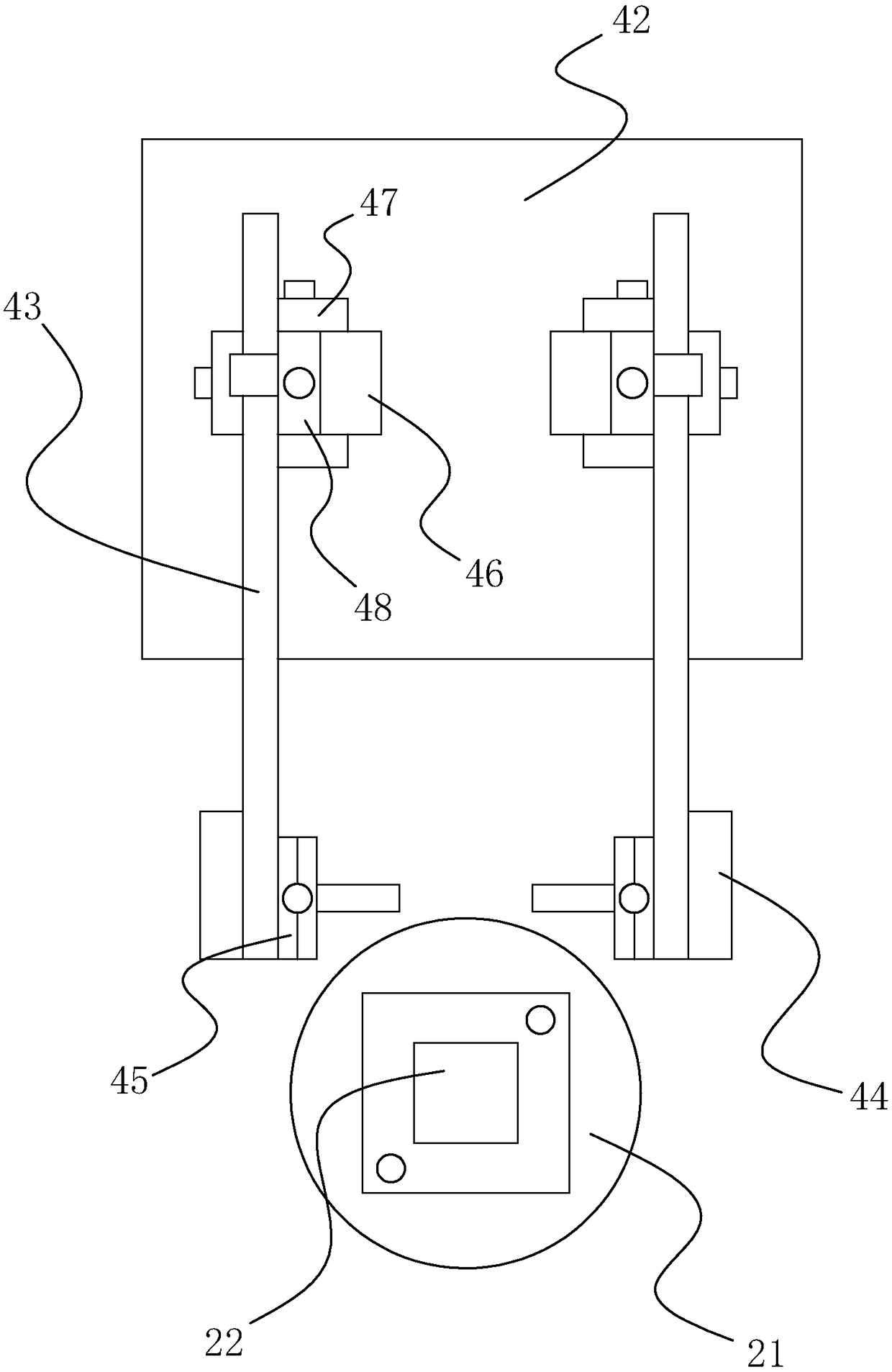
[0023] Such as figure 1 with figure 2 As shown, the first positioning assembly 2 includes a rotary table 21 arranged on the worktable 1 and a motor driving the rotary table 21 to rotate. The top of the rotary table 21 is provided with a protrusion 22 or a recess for fixing the base. The middle part of the base is provided with a hole for the vertical beam to pass through. After the vertical beam passes through the base, the connection of each side is a weld. The commonly used vertical beam is a rectangular cross-section, and the hole in the base is a rectangular hole. The weld seam There are four, two of which are parallel, and the welding assembly 4 first welds the two parallel welding seams. After welding, the rotary table 21 rotates to rotate the other two welding seams to the corresponding positions of the welding assembly 4 to continue welding. The base is also provided with a hole for easy screw installation, and the hole cooperates with the rectangular hole to pass th...


PUM


Abstract

The invention discloses a full-automatic rotary positioning and welding device for guard bar components. The full-automatic rotary positioning and welding device comprises a workbench for placement of a vertical beam and a base. First positioning assemblies for fixing the base, a second positioning assembly for fixing the vertical beam, a welding assembly and a protective assembly are arranged on the workbench. The full-automatic rotary positioning and welding device for the guard bar components achieves automatic welding of multiple side edges between the vertical beam and the base in the manner that a position-adjustable welding gun is matched with a rotary workpiece, full automation of welding is achieved, and the welding efficiency is very high. The welding position of the workpiece can be flexibly adjusted by matching a fixing structure of the workpiece and a position adjusting structure of the welding gun, and the welding flexibility is very high.

Description

technical field [0001] The invention relates to a fully automatic rotary positioning welding device between guardrail components. Background technique [0002] The existing spliced ​​guardrail is connected and fixed by splicing as a whole, thus avoiding the adverse effects caused by welding. However, welding is generally used at the position where the vertical beam and the base are connected. Because this position is the main bearing point, the welding connection is relatively stronger. However, the traditional welding method is done by manual welding, which is very inefficient and has potential safety hazards. In order to improve the welding efficiency between the vertical beam and the base, It is necessary to make further improvements to the existing welded structures. Contents of the invention [0003] The present invention aims to solve the technical problems mentioned above, and provides a fully automatic rotary positioning welding device between guardrail components...

Claims


Application Information

Patent Timeline
Patent Type & Authority Patents(China)
IPC IPC(8): B23K37/02B23K37/04B23K37/047B23K37/00
CPCB23K37/006B23K37/0211B23K37/04B23K37/047
Inventor 朱光泽
Owner 广东固朗新型材料有限公司
Learn More