Synchronous lifting device and material conveying device

A technology of synchronous lifting and material, applied in conveyors, conveyor objects, transportation and packaging, etc., can solve the problems of damaged life of related components, difficult accuracy requirements, complex action programs, etc., to improve service life and simple action programs. , the effect of reducing energy consumption

Inactive Publication Date: 2017-05-24
旭东机械(昆山)有限公司
View PDF6 Cites 4 Cited by
  • Summary
  • Abstract
  • Description
  • Claims
  • Application Information

AI Technical Summary

Problems solved by technology

Although it is feasible to realize synchronous drive by means of electronic control compensation, this design requires that the relevant components of the load-bearing base plate on both sides must have high coordination accuracy, and the synchronization of the motors on both sides must be ensured, resulting in high cost and poor operation. complicated program
It is also limited by the difficulty in meeting the precision requirements of related processed parts, and the existing technical methods are likely to cause damage to related components and insufficient life span

Method used


Image

  • Synchronous lifting device and material conveying device
  • Synchronous lifting device and material conveying device
  • Synchronous lifting device and material conveying device

Examples


Embodiment 1

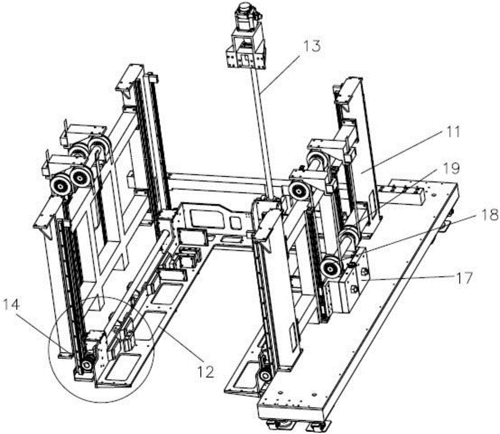
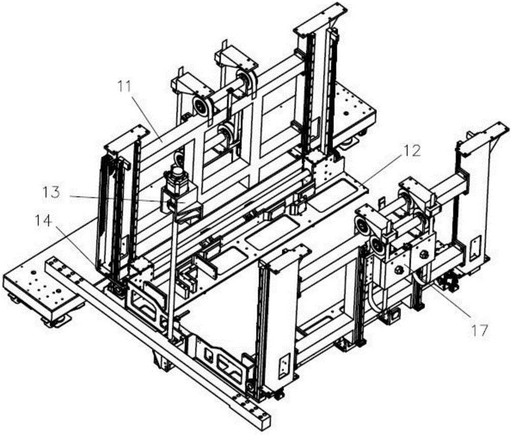
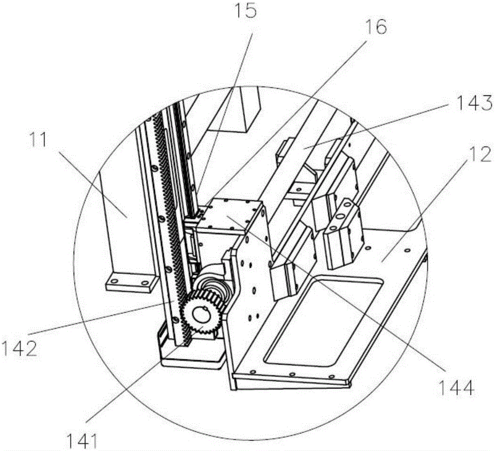
[0034] Please also see Figure 1 to Figure 5 , as shown in the figure, a synchronous lifting device is arranged at the input end of the conveying line 20. The synchronous lifting device 10 includes a frame 11, a lifting frame 12 for placing materials inside the frame 11, and a driving lifting frame 12. The driving mechanism 13 of material frame 12 vertical lifting; The relative both sides on the lifting material frame 12 are provided with linkage mechanism 14, and every group of linkage mechanism comprises two transmission parts that are arranged before and after and the transmission shaft that connects two transmission parts, by adopting transmission shaft will The front and rear two transmission parts are connected, so that the linkage between the transmission parts is realized, and the front and rear positions of one side of the lifting material frame are guaranteed to move at the same time.

[0035] In the present invention, the driving material frame is a rectangular stru...

Embodiment 2

[0047] All the other are the same as in Embodiment 1, the difference is that the lifting material frame 12 has four sides, the linkage mechanism 14 is three groups arranged on the three sides of the lifting material frame, and the output end of the driving mechanism 13 is connected to any side of any linkage mechanism. On one gear, this gear forms a driving gear, and the remaining gears are driven gears. Preferably, the joints of two adjacent groups of linkage mechanisms are in the form of gear meshing, and the gears at this place are 45-degree bevel gears. A transmission member is provided or a conveyor belt is wound around the two gears to transmit the rotation, and there is no specific limitation.

[0048] In addition, the driving mechanism can also be arranged in the middle of the side where no linkage mechanism is arranged, and the specific method is not limited.

Embodiment 3

[0050] All the other are the same as Embodiment 1, the difference is that the linkage mechanism 14 is four groups arranged around the lifting material frame 12, and the output end of the drive mechanism 13 is connected on any gear of any linkage mechanism 14, and the gear forms a driving mechanism. Gears, the rest of the gears are driven gears, preferably the joints of two adjacent groups of linkage mechanisms are in the form of gear meshing, and the gears at this place are 45-degree bevel gears. In other embodiments, a transmission member can also be provided between the two gears or a conveyor belt can be wound around the two gears to transmit the rotation, which is not specifically limited.


PUM


Abstract

The invention discloses a synchronous lifting device and a material conveying device. A driving mechanism is adopted for being matched with a linkage mechanism for acting, a lifting material frame is synchronously lifted wholly along with the driving mechanism when the driving mechanism runs, under the condition that the cost is reduced, synchronous running stability and reliability are guaranteed, and the motion program is simple; and in addition, the mechanism accuracy has a certain fault tolerance, and the service life of elements is greatly prolonged. A balance weight mechanism is arranged, upward pull force is applied to the lifting material frame when materials are lifted, the weight of the lifting material frame can be offset, the load of the driving mechanism is reduced, and energy consumption is reduced.

Description

technical field [0001] The invention belongs to the technical field of material lifting and feeding, and in particular relates to a synchronous lifting device. Background technique [0002] At present, in the process of large-scale material transportation, in order to improve work efficiency, a lifting device is usually installed at the front end of the conveying line, and the lifting device drives the pallet to move up and down to realize the purpose of conveying and loading materials upwards. [0003] In the prior art, such as the conveying of boxes, usually a plurality of boxes are stacked on the hydraulic trolley, and the boxes are transported to the lifting device by the hydraulic trolley. The lifting device usually includes a lifting material frame and a driving mechanism. After the box is placed in the lifting material frame, the driving mechanism gives the lifting material frame an upward force to drive the material on it to the top of the lifting device to push it t...

Claims


Application Information

Patent Timeline
Patent Type & Authority Applications(China)
IPC IPC(8): B65G47/57
CPCB65G47/57B65G2201/0267
Inventor 陆春锋代德松
Owner 旭东机械(昆山)有限公司
Why Eureka
Try Eureka