Pipeline gas adding resistance reduction slurry conveying device

A mud and pipeline technology, which is applied in the field of pipeline gas filling and drag reduction mud transportation equipment, can solve the problems of short transportation distance, pipeline wear, high energy consumption, etc., and achieve the effect of reducing flow resistance and reducing hydraulic loss along the way

A mud and pipeline technology, which is applied in the field of pipeline gas filling and drag reduction mud transportation equipment, can solve the problems of short transportation distance, pipeline wear, high energy consumption, etc., and achieve the effect of reducing flow resistance and reducing hydraulic loss along the way

CN106697953AActive Publication Date: 2017-05-24绍兴市城投再生资源有限公司

Image

  • Pipeline gas adding resistance reduction slurry conveying device
  • Pipeline gas adding resistance reduction slurry conveying device
  • Pipeline gas adding resistance reduction slurry conveying device

Examples


Embodiment 1

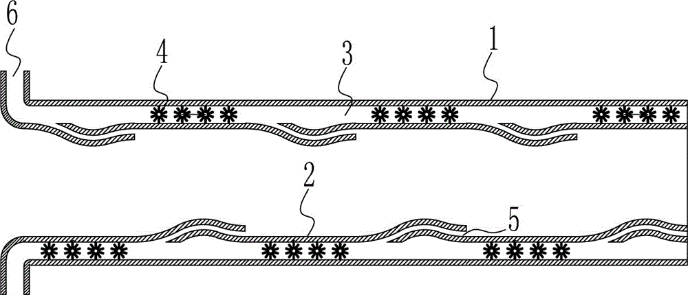
[0031] A pipeline gas filling and drag reduction transporting mud device, such as Figure 1-2 As shown, it includes an outer pipe wall 1, an inner pipe wall 2, a high-pressure air passage 3, a high-frequency vibrator 4, an air film generation passage 5 and a high-pressure air inlet 6, and the space between the outer pipe wall 1 and the inner pipe wall 2 is a high pressure The air channel 3 is provided with a high-frequency vibrator 4 inside the high-pressure air channel 3 , an air film generating channel 5 is provided on the inner pipe wall 2 , and the high-pressure air inlet 6 is connected with the high-pressure air channel 3 .

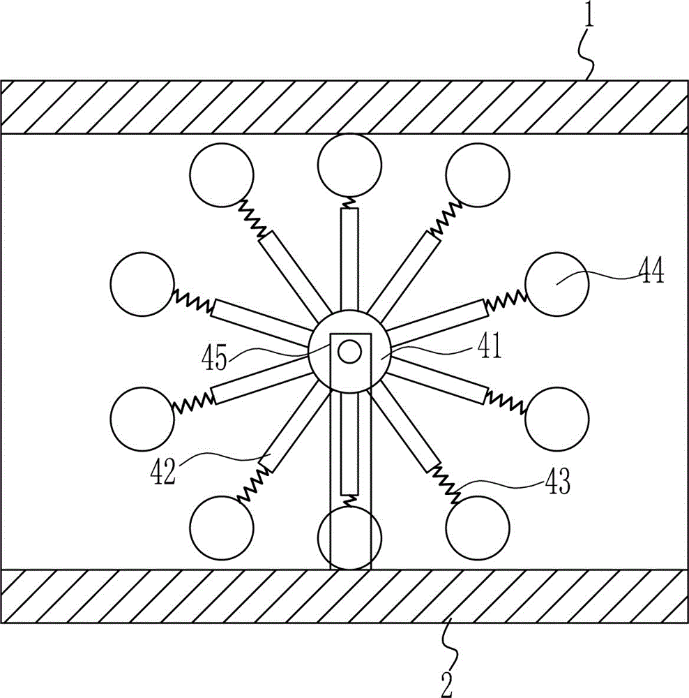
[0032] The high-frequency vibrator 4 includes a vibrating turntable I41, a vibrating blade 42, a vibrating spring I43, a vibrating steel ball 44 and a vibrating support 45, the vibrating support 45 is installed on the inner tube wall 2, and the vibrating turntable I41 is installed on the vibrating support 45 Vibration blades 42 are installed on the v...

Embodiment 2

[0037] A pipeline gas filling and drag reduction transporting mud device, such as Figure 1-6 As shown, it includes an outer pipe wall 1, an inner pipe wall 2, a high-pressure air passage 3, a high-frequency vibrator 4, an air film generation passage 5 and a high-pressure air inlet 6, and the space between the outer pipe wall 1 and the inner pipe wall 2 is a high pressure The air channel 3 is provided with a high-frequency vibrator 4 inside the high-pressure air channel 3 , an air film generating channel 5 is provided on the inner pipe wall 2 , and the high-pressure air inlet 6 is connected with the high-pressure air channel 3 .

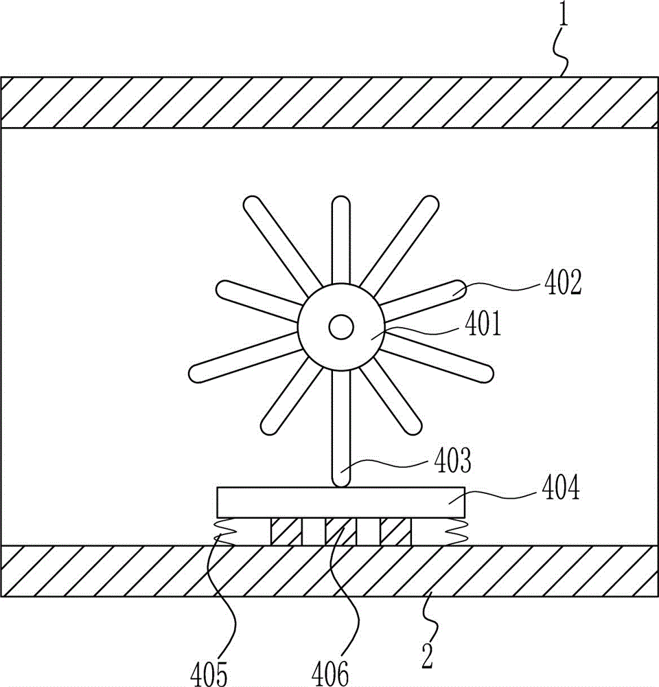
[0038] The high-frequency vibrator 4 includes a vibrating turntable II 401, a vibrating short blade 402, a vibrating long blade 403, a vibrating platform 404, a vibrating spring II 405 and a vibrating block 406. Short vibration blades 402 and long vibration blades 403 are installed. A vibration platform 404 is provided below the vibration turntable I...


PUM


Abstract

The invention belongs to the technical field of pipeline slurry conveying, and relates to a pipeline gas adding resistance reduction slurry conveying device. The pipeline gas adding resistance reduction slurry conveying device achieves the technical aims that flowing resistance of slurry in the pipeline is reduced, and hydraulic losses of the slurry along the way are reduced; in order to achieve the aims, the pipeline gas adding resistance reduction slurry conveying device comprises an outer pipe wall, an inner pipe wall, a high-pressure gas way, a high-frequency vibrator, a gas film generation way and a high-pressure air inlet; the high-pressure gas way is arranged between the outer pipe wall and the inner pipe wall, the high-frequency vibrator is arranged in the high-pressure gas way, the gas film generation way is arranged on the inner pipe wall, and the high-pressure air inlet is connected with the high-pressure gas way; the defects that the flowing resistance of the slurry in the pipeline is large, and hydraulic lowering along the way is rapid are overcome, and the effects that the flowing resistance of the slurry in the pipeline is reduced, and the hydraulic losses of the slurry along the way are reduced are achieved.

Description

technical field [0001] The invention belongs to the technical field of pipeline mud transportation, and relates to a pipeline gas-filling and drag-reducing mud transportation device. Background technique [0002] On the dredger for channel dredging, the dredging pump sucks up the cut mud, and transports the mud from the dredging point to the far-distance sludge storage and processing point through the large-diameter and long-distance mud pipeline. Due to the characteristics of the dredged mud, which has many components, high concentration, and large flow rate, the mud is in a multiphase flow state when it is transported in the pipeline, and its flow velocity is greatly disturbed and the flow field is complex. As a result, the flow resistance of mud in the pipeline is large, and the hydraulic pressure drop along the way is fast, which often leads to pipeline wear, blockage, short transportation distance and high energy consumption of the dredger's mud transportation system, w...

Claims


Application Information

Patent Timeline
24 May 2017
Publication
CN106697953A
IPC
B65G53/16; B65G53/34
Inventors
不公告发明人