Energy-saving scraper blade conveying device for dust removal

A conveying device and scraper technology, which is applied in the field of energy-saving scraper conveying devices for dust removal, can solve the problems of increasing conveying resistance, reducing conveying efficiency, and increasing energy consumption, so as to reduce equipment occupation space, improve conveying efficiency, and reduce operating noise Effect

Inactive Publication Date: 2015-12-02
JIANGSU CHANGJING ENVIRONMENTAL PROTECTION TECH
View PDF10 Cites 4 Cited by
  • Summary
  • Abstract
  • Description
  • Claims
  • Application Information

AI Technical Summary

Problems solved by technology

However, the bending part of the powder transportation box in this application can only be made into a straight line bending. At the bending part, it is difficult for the scraper to scrape all the powder, resulting in easy accumulation of material at the bending part, which is easy to cause Blockage; in this application, the reversing gear located on the outside of the chain must be used for reversing. The reversing gear is easy to block the operation of the scraper. The inclination angle of the transport box needs to be gentler, resulting in a longer conveying distance of the powder transport box, which increases the equipment footprint and reduces the conveying efficiency; in addition, the chain drive is adopted, and the scraper will be transported with the powder during movement. The box produces friction, which increases the conveying resistance, thereby increasing energy consumption, and the operation stability is poor, which will generate greater noise; in addition, the friction between the scraper and the box will generate heat or even sparks, which is harmful to flammable There are certain safety hazards in the transportation of powder materials (such as wood chips, etc.)

Method used


Image

  • Energy-saving scraper blade conveying device for dust removal
  • Energy-saving scraper blade conveying device for dust removal

Examples


Embodiment

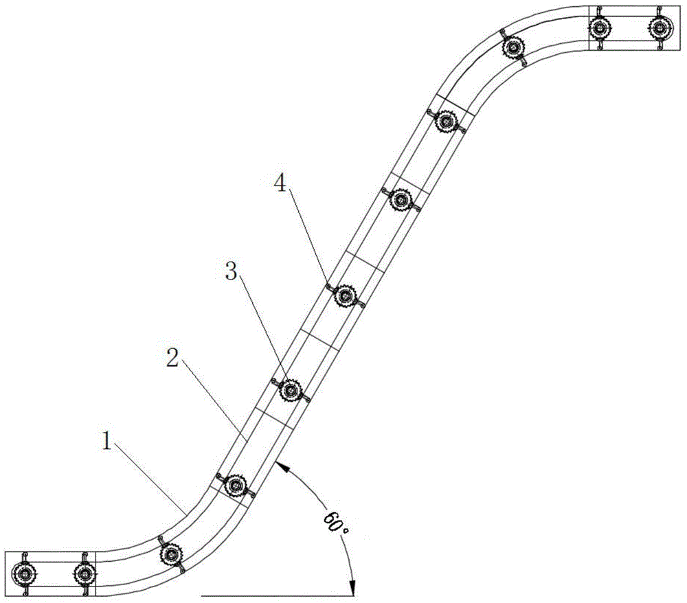
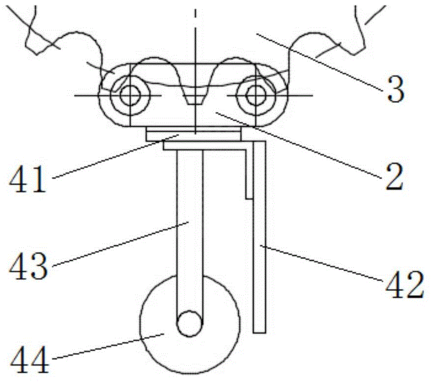
[0030] combine figure 1 and figure 2As shown, an energy-saving scraper conveying device for dust removal in this embodiment includes a conveying box 1, a chain transmission mechanism installed in the conveying box 1, and several scrapers 42 arranged at intervals on the chain transmission mechanism. The mechanism is used to drive the scraper 42 to rotate circularly in the conveying box 1, so as to transport the dust collected by the dust collector from the bottom of the conveying box 1 to the top of the conveying box 1, so as to realize efficient dust conveying. Different from the prior art, there is an inclination α between the conveying box 1 and the horizontal plane in this embodiment, and the inclination α can reach 60°, and the turning part of the conveying box 1 is a circular arc transition, adopting a large inclination angle The structure of the conveying box 1 reduces the conveying distance, reduces the space occupied by the equipment, and improves the conveying effic...


PUM


Abstract

The invention discloses an energy-saving scraper blade conveying device for dust removal, and belongs to the field of dust removal equipment. The energy-saving scraper blade conveying device comprises a conveying box body, a chain transmission mechanism mounted in the conveying box body and a plurality of scraper blades which are arranged on the chain transmission mechanism at intervals, wherein an inclined angle alpha is provided between the conveying box body and the horizontal plane; the turning part of the conveying box body is in circular-arc transition; the chain transmission mechanism comprises a plurality of groups of chain wheels which are arranged according to the conveying track of the conveying box body at intervals, a ring-shaped chain which is engaged with the chain wheels and is matched with the conveying track of the conveying box body in shape, and a motor which drives the chain wheels to rotate; the scraper blades are mounted on the chain at intervals; and rollers which are higher than the scraper blades are further arranged on mounting positions of the scraper blades. The energy-saving scraper blade conveying device reduces equipment occupied space, and improves dust conveying efficiency; the scraper blades do not directly generate friction with the conveying box body, so that conveying resistance is reduced, energy consumption is reduced, operation noises are reduced, manufacturing cost is reduced, and the dust conveying stability and safety are improved.

Description

technical field [0001] The invention relates to a conveying device, in particular to an energy-saving scraper conveying device for dust removal. Background technique [0002] Dust collectors are mainly used to capture fine, dry, non-fibrous dust, such as wood chips. When the dust removal equipment is working, the dust generally enters the dust collector through the dust suction pipe, and the dust falls into the bottom of the dust collector. Among them, the dust as a pollutant must be treated later. In some cases, due to the space conditions of the site installation Due to restrictions, the bottom of the dust collector cannot be installed or stored in a silo for centralized recovery of dust, which will inevitably lead to the inability to effectively recover the dust absorbed by the dust collector, which is not conducive to production. In this case, it is generally necessary to transport the dust collected at the bottom of the dust collector to the silo for centralized recove...

Claims


Application Information

Patent Timeline
Patent Type & Authority Applications(China)
IPC IPC(8): B65G19/18
Inventor 沈鑫
Owner JIANGSU CHANGJING ENVIRONMENTAL PROTECTION TECH
Why Eureka
Try Eureka