Underwater dredging head in type of twisting flying rope
A cutter suction, dredging ship technology, applied in mechanically driven excavators/dredgers, etc., can solve the problems of difficult to implement sludge, large soil aggregates, low slurry concentration, etc. high-efficiency effect
- Summary
- Abstract
- Description
- Claims
- Application Information
AI Technical Summary
Problems solved by technology
Method used
Image
Examples
Embodiment 1
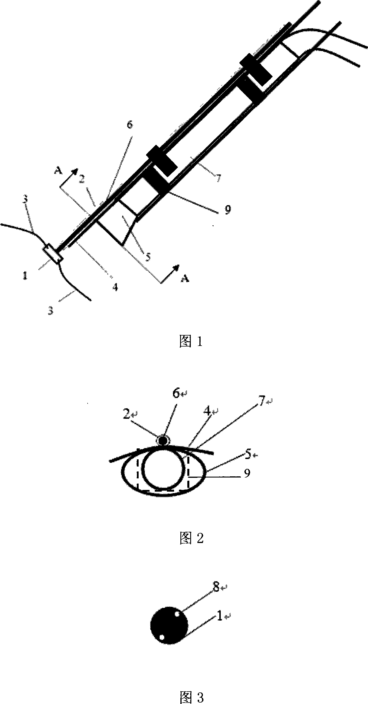
[0021] As shown in Figures 1-3, this embodiment includes: a flywheel 1, a transmission rod 2, a rope 3, a water retaining plate 4, and a mud suction port 5, the rope 3 is arranged on the edge of the flywheel 1, and the transmission shaft in the transmission rod 2 6 drives the flywheel 1, the water retaining plate 4 is located at the upper edge of the dredging port 5, and the transmission rod 2 is located at the support 9 of the dredging port 5 and the dredging vessel or the dredging pipe 7 of the equipment.
[0022] Described flywheel 1, its edge is provided with 2 cut small holes 8, allows 2 ropes to pass through respectively, and flywheel 1 is arranged on the transmission shaft 6 of transmission rod 3, relies on the transmission shaft in transmission rod 3 to rotate at a high speed, and its rotating speed is 8000 times / min. Described flywheel 1 diameter 5 centimetres. The flywheel 1 is arranged in front of the dredging port with a distance of 2 times the size of the dredged...
Embodiment 2
[0032] This embodiment includes: flywheel 1, transmission rod 2, rope 3, water retaining plate 4, mud suction port 5, rope 3 is arranged on the edge of flywheel 1, transmission shaft 6 in the transmission rod 2 drives flywheel 1, water retaining plate 4 Located on the upper edge of the dredging port 5, the transmission rod 2 is arranged on the support 9 of the dredging port 5 and the dredging pipe 7 of the dredging ship or equipment.
[0033] Described flywheel 1, its edge is provided with 6 small holes 8, allows 6 ropes to pass through respectively, flywheel 1 is arranged on the transmission shaft of transmission rod 3, relies on the transmission shaft 6 in transmission rod 2 to rotate at a high speed, and its rotating speed is 6500 times / min. Described flywheel 1 diameter 10 centimetres. The flywheel 1 is arranged in front of the dredging port with a distance of 4 times the size of the dredged port, and is arranged in front of the water baffle with a distance of 2 times the...
Embodiment 3
[0043] As shown in Figure 1, the present embodiment comprises: flywheel 1, transmission rod 2, rope 3, suction port 5, rope 3 is located at the edge of flywheel 1, transmission shaft 6 in transmission rod 2 drives flywheel 1, transmission rod 2 It is arranged on the bracket 9 of the dredging port 5 and the dredging pipe 7 of the dredging ship or equipment.
[0044] Described flywheel 1, its edge is provided with 10 small holes 8, allows 10 ropes to pass through respectively, and flywheel 1 is arranged on the transmission shaft of transmission rod 3, relies on transmission shaft 7 in transmission rod 2 to rotate at a high speed, and its rotating speed is 500 times / min. Described flywheel 1 diameter is 25 centimetres. The flywheel 1 is arranged in front of the suction port with a distance of 3.5 times the size of the suction port.
[0045] The transmission rod 2 is arranged on the dredging port 5 and the dredging vessel or the dredging pipe 7 of the equipment, and the transmis...
PUM
 Abstract
Description
Claims
Application Information
 - R&D
- Intellectual Property
- Life Sciences
- Materials
- Tech Scout
- Unparalleled Data Quality
- Higher Quality Content
- 60% Fewer Hallucinations
Browse by: Latest US Patents, China's latest patents, Technical Efficacy Thesaurus, Application Domain, Technology Topic, Popular Technical Reports.
© 2025 PatSnap. All rights reserved.Legal|Privacy policy|Modern Slavery Act Transparency Statement|Sitemap|About US| Contact US: help@patsnap.com

