Conveying roll with wire separation function

A conveying roller and function technology, which is applied in the field of plastic processing and conveying, can solve the problems of conveying roller failure and the inability of weaving yarn to be cleaned in time, so as to achieve the effect of preventing failure.

Active Publication Date: 2017-05-24
CHONGQING STRONG DUDLEY TECH DEV
View PDF5 Cites 2 Cited by
  • Summary
  • Abstract
  • Description
  • Claims
  • Application Information

AI Technical Summary

Problems solved by technology

[0004] The present invention intends to provide a conveying roller with a wire-removing function to solve the proble

Method used


Image

  • Conveying roll with wire separation function
  • Conveying roll with wire separation function
  • Conveying roll with wire separation function

Examples


Embodiment 1

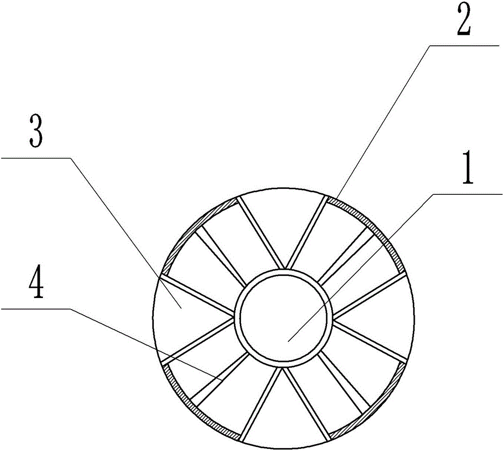
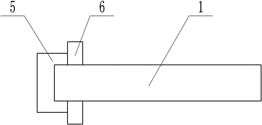
[0019] Example 1 as figure 1 Shown: a conveying roller with defiling function, including a conveying roller body, the conveying roller body includes an inner roller 1 and an outer roller 2, the outer roller 2 is arranged outside the inner roller 1, and a roller is arranged between the outer roller 2 and the inner roller 1 There are support rods 4, the outer roller 2 is provided with a gap, and the gap is provided with a fan-shaped air bag 3, the air bag 3 is installed on the inner roller 1, the arc edge of the air bag 3 is flush with the outer surface of the outer roller 2, and the inner roller 1 shaft There is a groove in the direction, and one end of the groove is connected to the outside, such as figure 2 As shown, the end of the inner roller 1 communicating with the outside is dynamically connected with an air pump 5 , and the inner roller 1 and the air pump 5 are sealed by a rotary dynamic sealing ring 6 .

[0020] When the woven bag is transferred from the forming mach...

Embodiment 2

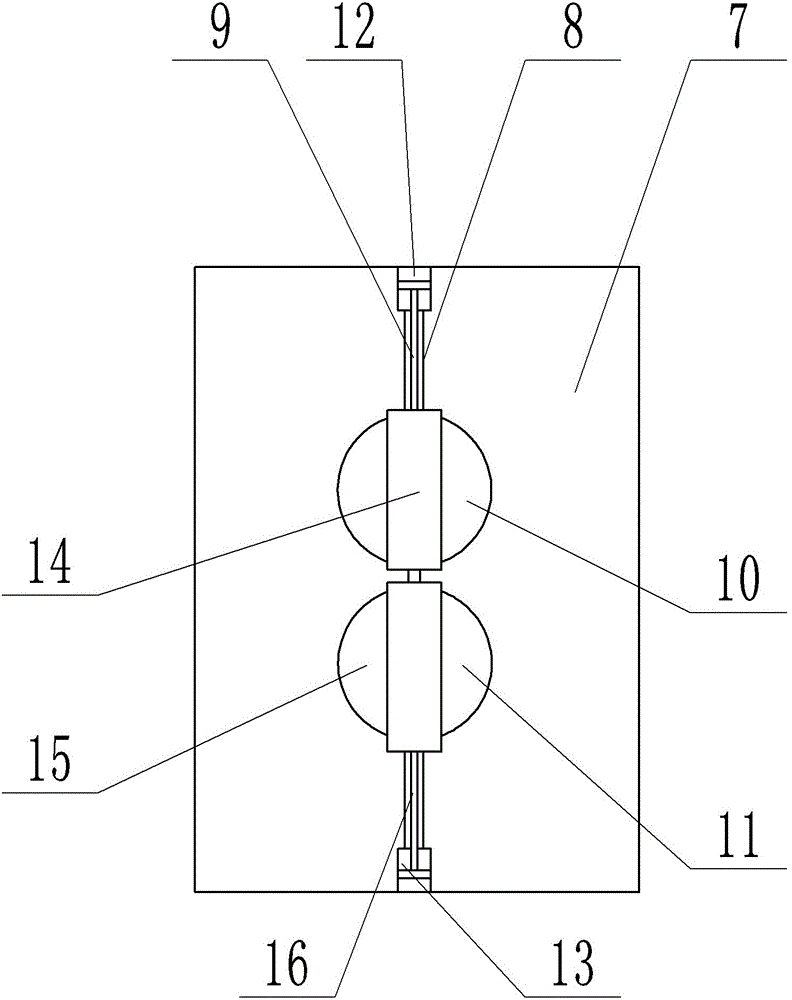
[0022] Such as image 3 As shown, the difference with Embodiment 1 is only that it includes a frame 7, the top of the frame 7 is connected with the first hydraulic cylinder 12 through the first piston rod 9, and the bottom of the frame 7 is connected with the second piston rod 16 through the second piston rod. Two hydraulic cylinders 13, a guide rail 8 is vertically arranged in the middle of the frame 7, a first base 14 and a second base 15 are slidably connected to the guide rail 8, and two conveying rollers are also included, namely an upper pressing roller 10 and a lower pressing roller 11 , the upper pressing roller is fixedly connected to the first base 14 , and the lower pressing roller 11 is fixedly connected to the second base 15 .

[0023] Changing the pressure of the hydraulic cylinder can make the upper pressure roller 10 and the lower pressure roller 11 slide up and down. When cleaning the braided yarn on the upper pressure roller 10, move the lower pressure roller...


PUM


Abstract

The invention discloses a conveying roll with a wire separation function. The conveying roll comprises a rack, a guide rail and a conveying roll body, wherein the guide rail is vertically arranged in the rack; the conveying roll body is connected on the guide rail in a sliding manner; the conveying roll body comprises an inner roll and an outer roll; the outer roll is arranged at the outer part of the inner roll; the two ends of the outer roll are connected on the guide rail in a sliding manner; supporting rods are arranged between the outer roll and the inner roll; the outer roll is provided with notches; fan-shaped air sacs are arranged at the notches; the air sacs are connected with the inner roll; and arc-shaped surfaces of the air sacs and the outer side surface of the outer roll are flush. Through the adoption of the scheme, a woven wire wound on the outer roll can be automatically separated timely, and the conveying roll is prevented from breaking down.

Description

technical field [0001] The invention belongs to the technical field of plastic processing and conveying. Background technique [0002] In the production process of plastic woven bags, the raw materials are plasticized, and the raw materials are extruded through the die after shearing and plasticizing in the extruder to form embryonic filaments. Due to the speed difference between the conveyor rollers, it is easy to cause the poor quality braided yarn to be broken and wound on the conveyor roller. [0003] Moreover, when the woven bag comes out of the molding machine, the temperature of the woven bag is very high, and then it is conveyed by the conveying roller, and some poor-quality braided yarns are wound on the conveying roller. , It takes a long time to wait for the braided wire to cool down before the staff can take cleaning measures. At this time, there are too many braided wires wound on the conveyor roller, which may cause the conveyor roller to malfunction. Conten...

Claims


Application Information

Patent Timeline
IPC IPC(8): B65H27/00B65H20/02
CPCB65H20/02B65H27/00B65H2301/531B65H2404/142
Inventor 丁小容
Owner CHONGQING STRONG DUDLEY TECH DEV
Why Eureka
Try Eureka