Manufacturing method of carbon fiber mesh composite board and concrete continuous beam

A composite plate, carbon fiber technology, applied in the direction of formwork/template/work frame, joists, girders, etc., can solve the problems such as the inability to fully exert the bearing capacity of carbon fiber materials, the adverse effects of structural bearing capacity, and the easy softening of organic glue. The effect of reducing self-weight, reducing time and material, preventing peeling

Active Publication Date: 2017-05-24
HUNAN UNIV
View PDF10 Cites 2 Cited by
  • Summary
  • Abstract
  • Description
  • Claims
  • Application Information

AI Technical Summary

Problems solved by technology

[0004] At present, there are certain problems when using carbon fiber reinforced composite materials to strengthen concrete structures. On the one hand, this material needs to be bonded to the surface of the structure by organic glue to make it final. On the other hand, the use of carbon fiber reinforced composite material layers is prone to peeling damage, and the bearing capacity of carbon fiber materials cannot be fully utilized

Method used


Image

  • Manufacturing method of carbon fiber mesh composite board and concrete continuous beam
  • Manufacturing method of carbon fiber mesh composite board and concrete continuous beam
  • Manufacturing method of carbon fiber mesh composite board and concrete continuous beam

Examples


Embodiment Construction

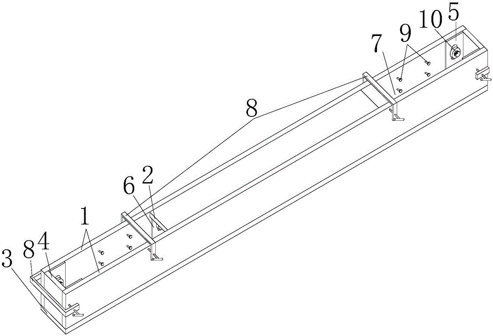
[0025] The present invention will be further described below in conjunction with the accompanying drawings. as attached figure 1 Shown is a carbon fiber grid composite plate concrete continuous beam and a manufacturing method thereof, including the following steps:

[0026] 1. Lay the mold accurately;

[0027] 2. Arrange the bottom positioning strip, whose thickness is consistent with the thickness of the protective layer at the bottom of the board;

[0028] 3. Prepare the steel fiber reinforced cement matrix, and pour it on the formwork until the upper surface of the positioning strip, as the bottom protection layer of the slab;

[0029] 4. Arrange each layer of carbon fiber braided mesh: place the bottom carbon fiber braided mesh on the bottom positioning bar, and arrange new positioning bars between each layer of carbon fiber braided mesh, so that the carbon fiber braided mesh is symmetrically distributed along the thickness direction of the plate;

[0030] 5. Fix, tight...


PUM


Abstract

The invention discloses a manufacturing method of a carbon fiber mesh composite board and concrete continuous beam. A member comprises side plates, a top plate, a bottom plate, end plates, U-shaped steel hoops, a U-shaped steel hoop with a flange, and concrete, wherein the side plates, the top plate and the bottom plate are respectively made of carbon fiber mesh composite boards, and the end plates are made of common cement boards; a shear connector is embedded into the single side of the carbon fiber mesh composite board to increase the adhesion force between the concrete and the composite board; the side plates and the bottom plate are connected by the U-shaped steel hoops; the end plates are positioned at the inner end of a groove which is formed by the side plates and the bottom plate, and are clamped by G-shaped clamps; the side plates are fixed by the G-shaped clamps in each bay; the top plate is overlapped on the flange of the U-shaped steel hoop. The concrete is cast into the groove which is defined by the side plates, the top plate, the bottom plate and the end plates, and is cured, so as to form the continuous beam. The member has the advantages that no formwork is needed; the self weight is light, the durability is good, and the construction is simple.

Description

technical field [0001] The invention relates to a civil building concrete continuous beam and a manufacturing method thereof, in particular to a manufacturing method of a carbon fiber grid composite plate concrete continuous beam. Background technique [0002] With the advancement of my country's urbanization process, the application range of reinforced concrete is becoming wider and wider. However, under the long-term unfavorable natural environment and use conditions, although reinforced concrete structures can meet the strength requirements, they are damaged due to poor durability. Engineering examples abound. Due to structural cracks caused by construction, use and environment, the concrete gradually loses protection to the internal steel bars. When harmful corrosive gases enter the structure, the acidic substances combined with water will corrode the steel bars, resulting in degradation of the mechanical properties of the steel bars and damage to the performance of the c...

Claims


Application Information

Patent Timeline
Patent Type & Authority Applications(China)
IPC IPC(8): E04C3/29E04G13/04
CPCE04C3/29E04G13/04
Inventor 杜运兴张忻颖周芬
Owner HUNAN UNIV
Why Eureka
Try Eureka