Air purifying door

A technology for air purifying doors and cavities, applied in door leaves, windows/doors, chemical instruments and methods, etc., can solve the problems of difficult to guarantee air purification effect, and achieve the effect of simple structure

Active Publication Date: 2017-05-24
信宜市现代中兴门业有限公司
4 Cites 4 Cited by

AI-Extracted Technical Summary

Problems solved by technology

However, due to the lack of indoor air flow, if the position of the activated carbon bag ...

Abstract

The invention aims to provide an air purifying door capable of purifying indoor air. The air purifying door comprises a door body comprising an inner door board and an outer door board, a cavity for containing an adsorption bag is formed in the door body, the inner door board is provided with a moving door at a position corresponding to the cavity, the moving door is composed of a main board, a bottom board below the main board and facing the cavity and side boards on two sides of the main board and facing the cavity, an upward folded edge is arranged on one side, facing the outer door board, of the bottom board, and the main board, the bottom board, the side boards and the folded edge form a limiting portion for limiting the adsorption bag; the bottom end of the main board is connected with the inner door board through a rotating shaft, and each of the main board of the moving door and the outer door board is provided with a ventilation hole at a position corresponding to the cavity. The air purifying door is simple in structure; by arranging an air circulating passage in the door and putting the adsorption bag convenient to replace in the same, air flowing through the passage can be purified effectively, so that the air purifying door is quite good for human health.

Application Domain

Dispersed particle separationVentilation arrangement +1

Technology Topic

Human healthIndoor air +3

Image

  • Air purifying door
  • Air purifying door
  • Air purifying door

Examples

  • Experimental program(1)

Example Embodiment

[0015] Example 1:
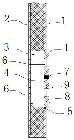
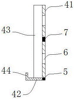
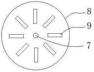
[0016] As shown in the figure, the air purification door of this embodiment includes a door body provided with an inner door panel 1 and an outer door panel 2. The door body is provided with a cavity 3 for accommodating the adsorption bag, and the inner door panel 1 is in the corresponding cavity 3 A movable door 4 is provided at the position where the movable door 4 is composed of a main board 41, a bottom plate 42 facing the cavity 3 under the main board 41, and side plates 43 facing the cavity 3 on both sides of the main board 41. The direction of the bottom plate 42 One side of the outer door panel 2 is provided with an upward folding edge 44. The main board 41, the bottom plate 42, the side plate 43 and the folded edge 44 constitute a limit part of the limit suction bag; the bottom end of the main board 41 is connected to the The inner door panel 1 is connected, and the main board 41 of the movable door 4 and the outer door panel 2 are provided with vent holes 6 at positions corresponding to the cavity 3.
[0017] The air purification door is provided with a passage for air circulation on the door, that is, the vent 6 of the outer door panel 2, the cavity 3, and the vent 6 of the inner door panel 1 are the air circulation channels. When the air flows through here, it must After passing through the adsorption bag placed in the cavity 3, the adsorption bag can be filled with activated carbon to adsorb pollutants in the air, thereby purifying the air to a certain extent. After the adsorption bag has been used for a long time, the movable door 4 can be opened, and the adsorption bag can be taken out of the cavity 3 for replacement. Since the adsorption bag is placed in the limiting part formed by the movable door 4, it is very convenient to take out and replace.
[0018] The center of the main board 41 of the movable door 4 is provided with a rotating shaft 7 perpendicular to the main board, and a circular adjusting plate 8 is installed through the rotating shaft 7. The ventilation holes 6 on the main board 41 are arranged radially with the rotating shaft 7 as the center. The adjusting plate 8 is provided with an auxiliary vent hole 9 corresponding to the position and shape of the vent hole 6 of the main board 41. When the adjusting plate 8 rotates around the rotating shaft 7, the vent hole 6 of the main board 41 can be opened or closed. When the auxiliary vent hole 9 on the adjustment plate 8 is rotated to coincide with the vent hole 6 of the main board 41, the air circulation channel is opened, and when the auxiliary vent hole 9 on the adjustment plate 8 rotates to be staggered with the vent hole 6 of the main board 41 , The adjusting plate 8 can close the air vent 6 of the main board 41, thereby closing the air circulation channel.

PUM

no PUM

Description & Claims & Application Information

We can also present the details of the Description, Claims and Application information to help users get a comprehensive understanding of the technical details of the patent, such as background art, summary of invention, brief description of drawings, description of embodiments, and other original content. On the other hand, users can also determine the specific scope of protection of the technology through the list of claims; as well as understand the changes in the life cycle of the technology with the presentation of the patent timeline. Login to view more.

Similar technology patents

Body condition measuring device

InactiveUS20050234351A1simple structure
Owner:DENSO CORP

Magnetic cooling apparatus and control method thereof

ActiveUS20130180263A1simple structure
Owner:SAMSUNG ELECTRONICS CO LTD

Dual-Drivetrain of Power-Assist Vehicle

InactiveUS20100181130A1enhance uphill momentumsimple structure
Owner:CHOU WEN CHENG

Classification and recommendation of technical efficacy words

  • Simple structure

Sharing system for air-conditioning coat

InactiveCN107440179ASimple structureeasy to wear
Owner:QINGDAO HAIER AIR CONDITIONER GENERAL CORP LTD

Feeding device of sorter of batteries plate

InactiveCN101357717ASimple structurecooperate well
Owner:NANJING NORMAL UNIVERSITY

Emergency parachuting device and method for multiple-rotor unmanned aerial vehicle

InactiveCN103895870Aavoid aircraft crashSimple structure
Owner:SOUTH CHINA AGRI UNIV +1
Why Eureka
Try Eureka