
Hydraulic drag reducer

A drag reducer and hydraulic technology, applied in the direction of drill pipe, casing, drill pipe, etc., can solve the problems of drilling and grinding speed limitation, bit application, tubing can't go down, etc., to ensure normal lifting and reduce friction Effect

Active Publication Date: 2019-03-12
PETROCHINA CO LTD
View PDF8 Cites 0 Cited by
  • Summary
  • Abstract
  • Description
  • Claims
  • Application Information

AI Technical Summary

Problems solved by technology

[0003] However, there are also many difficulties in the construction process of directional wells and horizontal wells, such as the difficulty in applying the pressure on bit during drilling, the difficulty in lifting and lowering the tubing during well completion, and the inability to effectively apply the bit pressure when grinding bridge plugs, etc.
The fundamental reason is that in directional wells and horizontal wells, due to the long-distance horizontal direction of the wellbore, most of the drill string or tubing string lies flat in the wellbore, and most of the drilling or lowering pressure is consumed in overcoming The frictional resistance of the drill string is high, so it is difficult for ground equipment to apply enough pressure to the drill bit to break rock or mill bridge plugs; at the same time, it is difficult for ground operation engineers to figure out the precise pressure at the drill bit, resulting in a significant impact on the drilling speed. big limit
In addition, in the tubing operation of well completion, due to the tubing itself is light in weight and highly flexible, the tubing may even fail to go down under harsh conditions, and cannot go down to the depth of the designed well, especially in coiled tubing operations. obvious

Method used


Image

  • Hydraulic drag reducer
  • Hydraulic drag reducer
  • Hydraulic drag reducer

Examples


Embodiment Construction

[0063] In order to have a clearer understanding of the technical solutions, objectives and effects of the present invention, the specific implementation manners of the present invention will now be described with reference to the accompanying drawings.

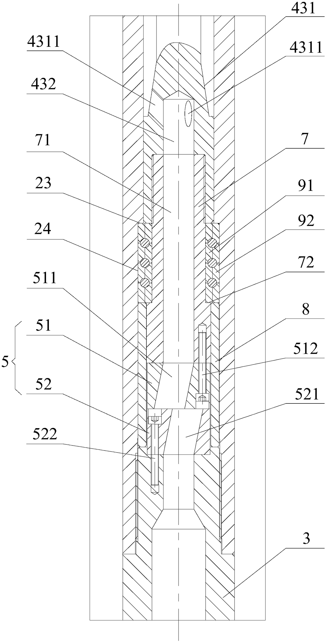
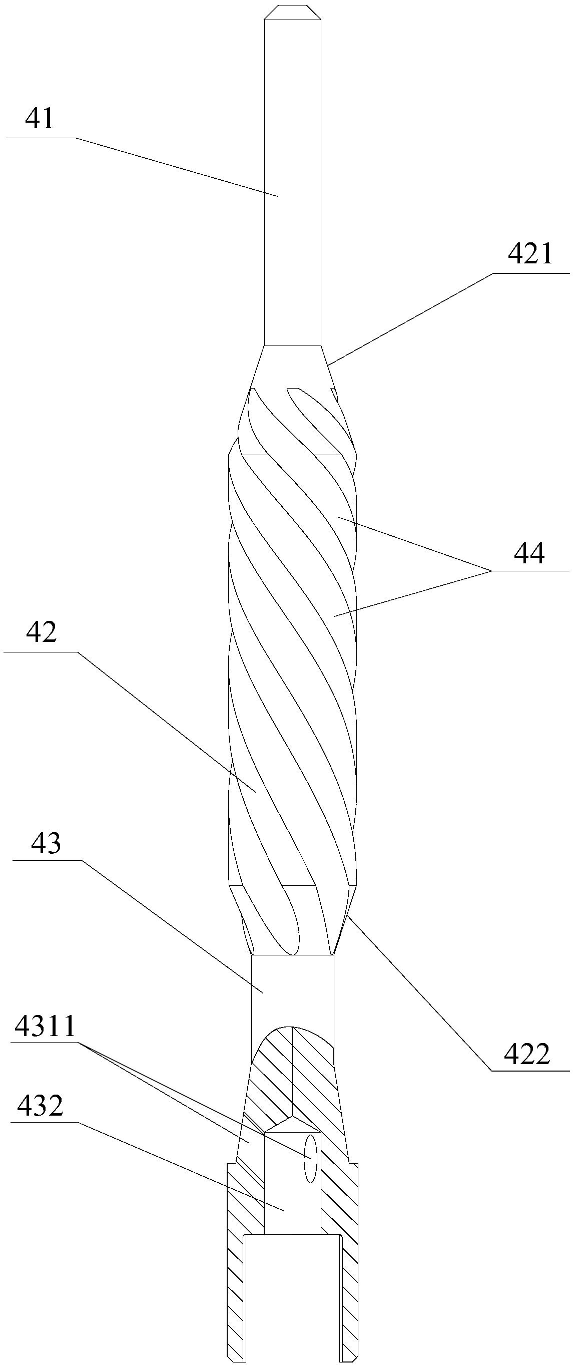
[0064] Such as figure 1 and figure 2 As shown, the present invention provides a hydraulic drag reducer, wherein the hydraulic drag reducer includes an upper joint 1, a housing 2 and a lower joint 3 connected in sequence from top to bottom, the upper joint 1, the housing 2 Both the upper joint and the lower joint 3 are tubular structures that penetrate up and down and are hollow inside. When in use, the fluid enters the interior of the housing 2 from the upper joint 1, reaches the lower joint 3 along the axial direction of the housing 2, and flows out from the lower joint 3. The inside of the housing 2 is provided with a rotor 4 and a disc valve assembly 5, the rotor 4 is rotatably arranged inside the housing 2, the outer wal...


PUM


Abstract

The invention provides a hydraulic drive anti-drag device. The device comprises an upper connector, a housing and a lower connector which are connected from top to bottom in sequence, the upper connector, the housing and the lower connector are all of an tube-shaped structure which is through from top to bottom and hollow internally, the inner portion of the housing is provided with a rotor and a disc valve assembly, the rotor can be rotatably arranged in the inner portion of the housing, the outer wall of the rotor is in contact with the inner wall of the housing in a fitting mode, the disc valve assembly is located below the rotor, and the disc valve assembly is connected to the rotor and the lower connector respectively. The hydraulic drive anti-drag device can change the sliding friction between a drill string and a well wall or a sleeve wall into vibration friction, accordingly the friction between drill string and the well wall or the sleeve wall is reduced, and thus the drilling speed and normal up and down of an oil tube are ensured.

Description

technical field [0001] The invention relates to the technical field of downhole tools, in particular to a hydraulic drag reducer. Background technique [0002] In the process of oil, natural gas and gas drilling and development, various technologies have become mature at this stage, and directional wells, horizontal wells, cluster wells, etc. are more and more widely used, and the design of such well body structures can be better and more accurate. Accurately drill to the ideal target position, improve the efficiency and output of oil extraction, and save the extraction cost to the greatest extent. [0003] However, there are also many difficulties in the construction process of directional wells and horizontal wells, such as difficulty in applying WOB during drilling, difficulty in lifting and lowering tubing during well completion, and inability to effectively apply WOB even when grinding bridge plugs. The fundamental reason is that in directional wells and horizontal wel...

Claims


Application Information

Patent Timeline
Patent Type & Authority Patents(China)
IPC IPC(8): E21B17/10
CPCE21B17/10
Inventor 肖云峰郭红峰李晗丽赵小强杨书港孟丽华胡波王岳王文明杜新军
Owner PETROCHINA CO LTD
Learn More