
Bridge fast load experimental test method

A load test and test method technology, which is applied in the direction of elasticity test, machine/structural component test, measuring device, etc., can solve the problems of low subjectivity, low accuracy, time-consuming and labor-intensive load test, and simplify the site Preparatory work, savings in test costs, and the effect of a simple loading method

Active Publication Date: 2017-05-24
山西省交通建设工程质量检测中心(有限公司)
View PDF5 Cites 27 Cited by
  • Summary
  • Abstract
  • Description
  • Claims
  • Application Information

AI Technical Summary

Problems solved by technology

[0002] Aiming at the problems that the detection algorithm in the Chinese bridge bearing capacity evaluation system is subjectively arbitrary, and the load test is time-consuming and laborious, and has a great impact on traffic, the invention proposes a quasi-static load test based on the model calibration technology of the measured strain influence line Compared with the detection method, this method has less subjectivity and higher accuracy, and is cheaper than the conventional load test method and has less impact on normal traffic. To a certain extent, it can replace the conventional load test, or as a detection method. An Intermediate Evaluation Method Between Algorithm and Traditional Load Test Method
[0003] Bridge load test is a test method directly loaded on the bridge to evaluate the mechanical performance of the bridge under the test load, but this method is time-consuming, laborious and costly, especially for old bridges, which are closed to traffic for a long time cause greater impact

Method used


Image

  • Bridge fast load experimental test method
  • Bridge fast load experimental test method
  • Bridge fast load experimental test method

Examples


Embodiment approach

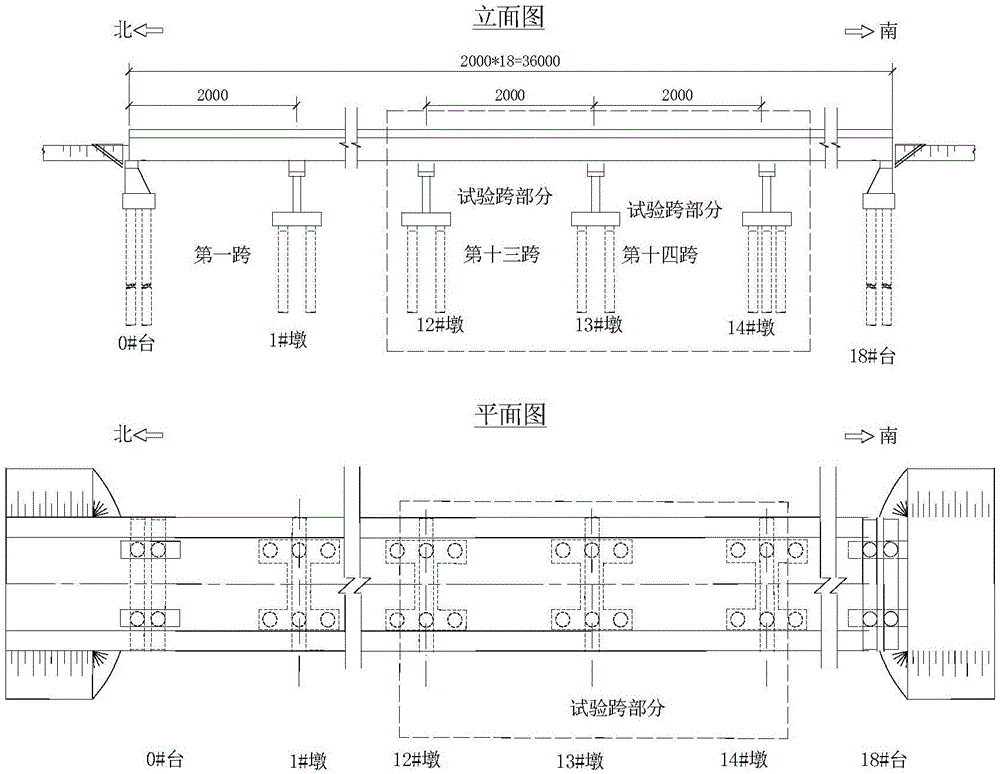
[0028] Combined with a continuous girder bridge, the bridge type is shown in figure 1 , to illustrate the implementation of the method, specifically as follows:

[0029] Step 1: Establish a finite element calculation model of the bridge according to the actual structural condition of the bridge;

[0030] To further explain step 1, the finite element calculation model of the bridge is based on the calculation principle of the displacement method, and its mechanical equation is:

[0031] [k][δ]=[F] (1)

[0032] where [k] is the total stiffness matrix of the structure, [δ] is the displacement matrix of the structure, and [F] is the load matrix. According to the above formula, related programs are written. Bridge static load tests generally involve multiple loading conditions, and different working conditions can be composed into a load matrix. Each column represents a different working condition, and each row represents a different node number.

[0033] Step 2: Displacement me...


PUM


Abstract

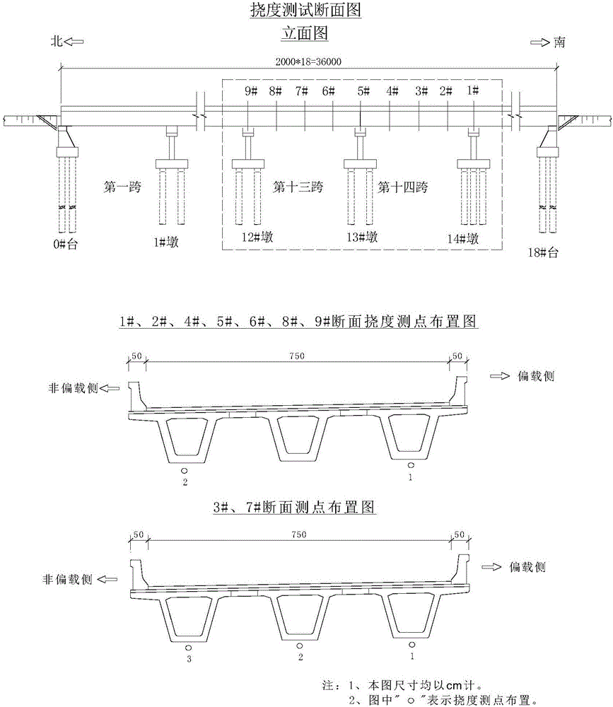
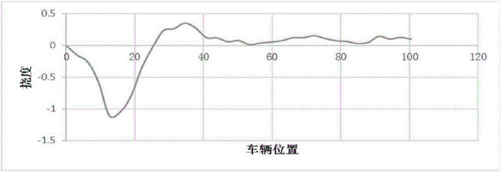
The invention provides a bridge fast load experimental test method comprising the following steps that a bridge finite element calculation model is established; a displacement measuring point is arranged at the key part of a test span; automobiles are slowly driven along the bridge deck, and the displacement influence line of the bridge is acquired; the actually measured curve of the bridge displacement influence line is drawn; the actually measured displacement value of high credibility is selected according to the actual result of the displacement influence test data; a multi-condition loading model is established according to the selected actually measured displacement value and the vehicle load corresponding position so as to perform finite element analysis and calculation; a displacement residual error expression is established, and a target function is formed to perform finite element model correction; and the deflection and the strain under the load test condition are calculated by adopting the corrected finite element model, the corrected model calculation value acts as the actually measured value and the uncorrected model calculation value acts as the theoretical value to calculate the verification coefficient and bridge carrying capacity evaluation is performed according to the specifications of bridge carrying capacity evaluation.

Description

technical field [0001] The invention belongs to the technical field of road and bridge quality detection, and in particular relates to a bridge rapid load test method. Background technique [0002] Aiming at the problems that the detection algorithm in the Chinese bridge bearing capacity evaluation system is subjectively arbitrary, and the load test is time-consuming and laborious, and has a great impact on traffic, the invention proposes a quasi-static load test based on the model calibration technology of the measured strain influence line Compared with the detection method, this method has less subjectivity and higher accuracy, and is cheaper than the conventional load test method and has less impact on normal traffic. To a certain extent, it can replace the conventional load test, or as a detection method. An intermediate evaluation method between the algorithm and the traditional load test method. [0003] Bridge load test is a test method directly loaded on the bridge...

Claims


Application Information

Patent Timeline
IPC IPC(8): G01M5/00
CPCG01M5/0008G01M5/005
Inventor 谢海龙张俊成曹蔚枝郭茂泉姬兵亮宋茂林罗鹏王彬何鑫
Owner 山西省交通建设工程质量检测中心(有限公司)
Learn More