Rock core holder for CT scanning

A core holder, CT scanning technology, applied in the direction of instruments, scientific instruments, material analysis using radiation, etc., can solve the problems such as the diameter is not small enough, the core cannot be scanned and imaged, the core holder is not resistant to high temperature, etc., and the guarantee is achieved. Effect of Alignment Accuracy

Pending Publication Date: 2017-05-24
CHINA UNIV OF PETROLEUM (BEIJING)
View PDF0 Cites 13 Cited by
  • Summary
  • Abstract
  • Description
  • Claims
  • Application Information

AI Technical Summary

Problems solved by technology

Most of the commonly used CT scanning methods at this stage are CT scans of exposed cores without core holders, which cannot consider formation conditions such as high temperature and high pressure, and the accuracy of the identification results needs to be verified
[0003] However, existing conventional core holders cannot be directly applied to CT scanning technology
First of all, the material of the conventional core holder cannot meet the requirements of non-attenuating penetration of X-rays, and cannot scan and image th

Method used


Image

  • Rock core holder for CT scanning
  • Rock core holder for CT scanning
  • Rock core holder for CT scanning

Examples


Example Embodiment

[0057] The details of the present invention can be understood more clearly in combination with the drawings and the description of the specific embodiments of the present invention. However, the specific embodiments of the present invention described herein are only used to explain the purpose of the present invention, and cannot be construed as limiting the present invention in any way. Under the teaching of the present invention, the skilled person can conceive any possible modifications based on the present invention, and these should be regarded as belonging to the scope of the present invention.

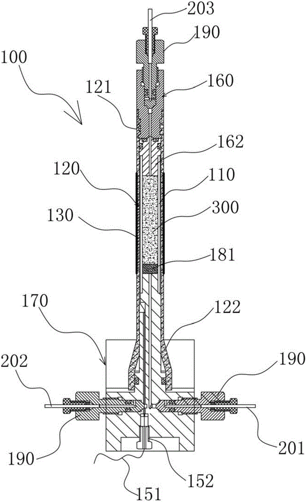
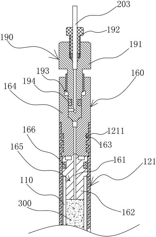
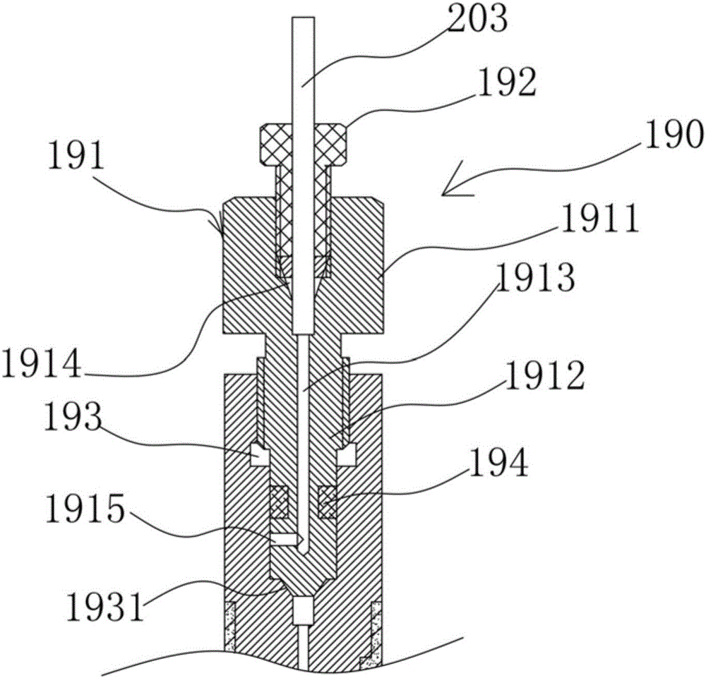
[0058] Please refer to figure 1 , Figure 4 with Figure 5 , figure 1 It is a schematic diagram of the structure of the core holder for CT scanning proposed by the present invention; Figure 4 It is a schematic diagram of the structure of the rubber sleeve of the present invention, Figure 5 for Figure 4 Partial enlarged view at middle A. Such as figure 1 As shown, the core holder...


PUM

PropertyMeasurementUnit
Lengthaaaaaaaaaa
Lengthaaaaaaaaaa
Outer diameteraaaaaaaaaa

Abstract

The invention provides a rock core holder for CT scanning and relates to the technical field of oil-gas field development. The rock core holder comprises a rubber sleeve, a carbon fiber cylinder and an electric heating sleeve which are sequentially arranged in a sleeved mode from inside to outside and are vertically through cylindrical bodies, an annular confining pressure cavity is formed between the rubber sleeve and the carbon fiber cylinder, a thermocouple is arranged in the confining pressure cavity, the thermocouple and an electrical heating sleeve are electrically connected with a temperature controller, the top end of the carbon fiber cylinder is in sealed connection with a plug, the bottom end of the carbon fiber cylinder is in sealed connection with a base, the plug, the base and the inner wall surface of the rubber sleeve define a core-containing holding cavity, a liquid flowing-out hole communicated with the holding cavity is formed in the plug, a liquid injection hole communicated with the holding cavity and a confining pressure liquid injection hole communicated with the confining pressure cavity are formed in the base, and the rock core holder can achieve stable core scanning under high-temperature and high-pressure conditions.

Description

Technical field [0001] The invention relates to the technical field of oil and gas field development, and particularly relates to a core holder for CT scanning used for studying the dynamic distribution characterization and change law of microscopic remaining oil at the pore throat scale. Background technique [0002] Accurately describing the distribution of remaining oil in the formation is a difficult task in oil field development. A clear understanding of the pore structure, particle properties, fluid distribution, and dynamic migration characteristics of two-phase fluids is the basic method for remaining oil research and the basis for improving oil recovery. In recent years, CT scanning technology has been widely used in oil and gas field development at home and abroad. CT scanning technology can perform multi-scale structural characterization of the core without causing damage to the internal structure of the rock. The application of this technology in the field of petrole...

Claims


Application Information

Patent Timeline
IPC IPC(8): G01N23/04
CPCG01N23/046
Inventor 李俊键高亚军赵玉云刘洋于馥玮苏航
Owner CHINA UNIV OF PETROLEUM (BEIJING)
Why Eureka
Try Eureka