
Eureka
For R&D, Eureka makes reading and utilizing patents & technical documents easy.
Eureka AIR
Designed for self-driven R&D workflows. Generate viable solutions, solve complex R&D challenges, empower your innovation with AI.

Eureka Materials
Designed for material experts only. Revolutionize your material R&D, from search, analyze, to developing new materials.

TechResearch
Generate reliable direction feasibility study reports for your R&D in just a few steps.

TechSeek
Discover and master advanced knowledge NOW. Basics, ideas, possibilities, all at once.

TechMind
As an expert in R&D Theories, TechMind can generates customized viable solutions instantly.

TechRisk
Analyze your overall solution with one click, know your potential R&D risks in advance.

TechMonitor
Get weekly tech updates, stay abreast of the latest tech innovations and key insights.
Upper supporting adjusting rack
A technology of adjusting frame and supporting plate, which is applied in the field of optical instruments and equipment, can solve problems such as time-consuming and labor-intensive changes in optical path angles, and achieve the effects of good reliability, high comfort and compact structure
- Summary
- Abstract
- Description
- Claims
- Application Information
AI Technical Summary
Problems solved by technology
Method used
Image

Examples
Embodiment 1
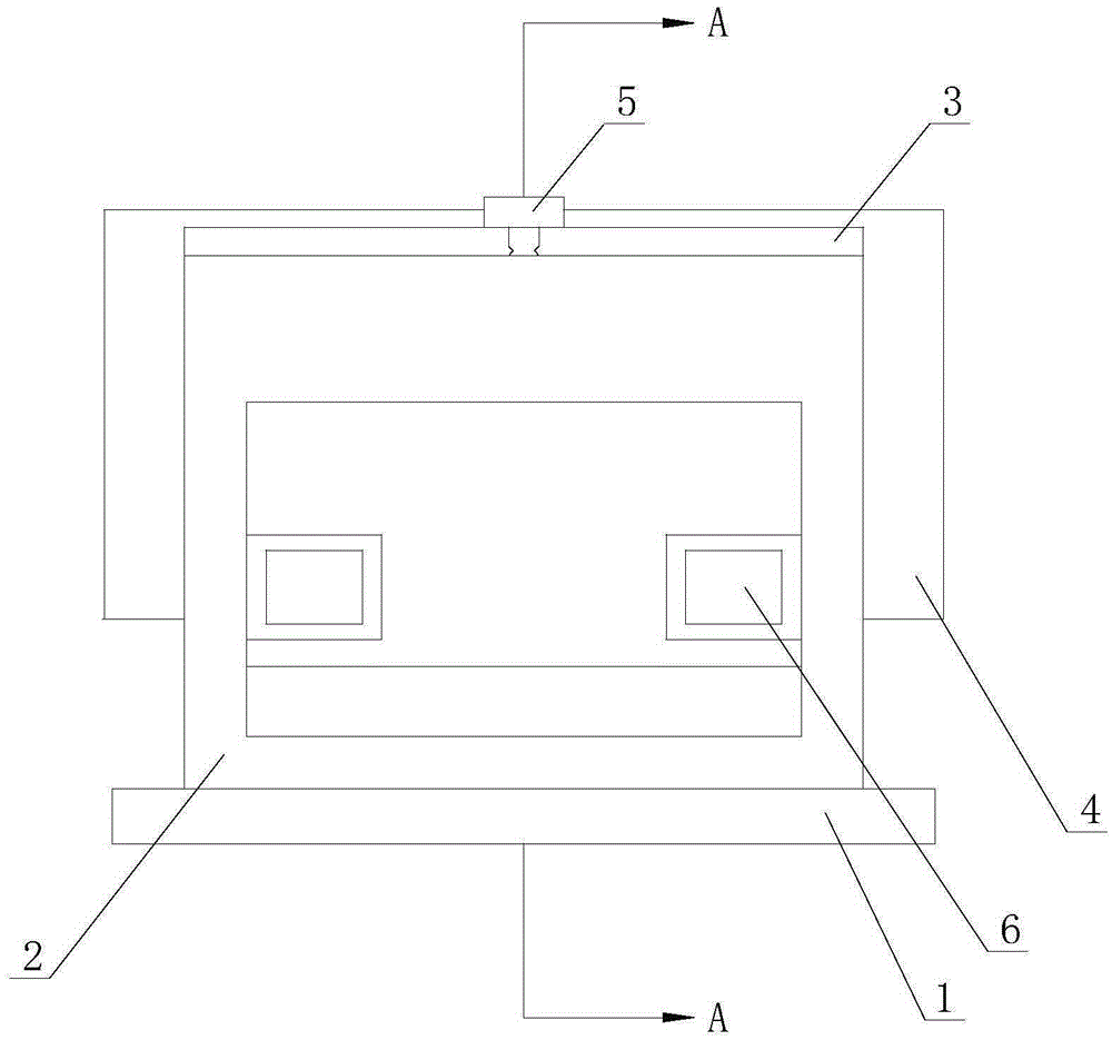
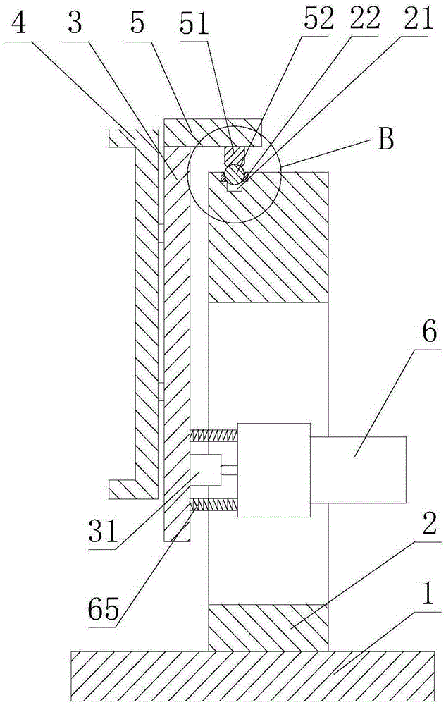
[0019] Such as Figure 1 to Figure 4 As shown, the upper support adjustment frame includes a base plate 1, an adjustment frame 2, a support plate 3, a mirror frame 4, an arm plate 5 and a drive assembly 6, the adjustment frame 2 is fixedly connected to the base plate 1, and the mirror frame 4 is fixedly connected to On the front end face of the support plate 3, there are two drive assemblies 6, which are fixedly connected to both sides of the adjustment frame 2 respectively. The drive assembly 6 includes a drive motor 61, a bellows coupling 62, a threaded rod 63 and a positioning plate 64, one coupling end of the bellows coupling 62 is fixedly connected to the output shaft of the drive motor 61, and the other coupling end of the bellows coupling 62 is fixedly connected to the threaded rod 63, so The positioning plate 64 is provided with a threaded hole passing through the positioning plate 64, the threaded rod 63 passes through the threaded hole, and the rear end surface of th...
Embodiment 2
[0021] This embodiment is further defined as follows on the basis of Embodiment 1, the drive assembly 6 also includes a speed reducer 66, the input end of the speed reducer 66 is connected to the output shaft of the drive motor 61, and the speed reducer The output end of 66 is connected to a coupling end of the bellows coupling 62 . If the drive motor 61 is used to directly act on the bellows coupling 62, a servo motor with high cost needs to be configured. In this embodiment, in order to reduce the cost, a reducer 66 is connected between the driving motor 61 and the bellows coupling 62, and the driving motor 61 acts on the bellows coupling 62 through the reducer 66 to reduce the speed and improve the adjustment accuracy Effect.
Embodiment 3
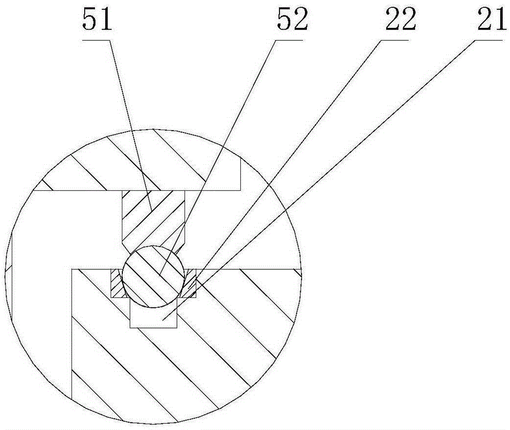
[0023] This embodiment is further defined as follows on the basis of Embodiment 1, the end of the threaded rod 63 is set as a spherical end, the connecting seat 31 is provided with a groove 34, the end of the threaded rod 63 is in contact with The grooves 34 are connected with spherical low pairs. If the end of the threaded rod 63 is divided into a left part and a right part with the longitudinal diameter, in order to prevent the end of the threaded rod 63 from breaking away from the groove 34 during adjustment, the open end of the groove 34 surrounding the end should be located at the end of the threaded rod 63 the right area of the head.
PUM
 Abstract
Description
Claims
Application Information
 - R&D Engineer
- R&D Manager
- IP Professional
- Industry Leading Data Capabilities
- Powerful AI technology
- Patent DNA Extraction
Browse by: Latest US Patents, China's latest patents, Technical Efficacy Thesaurus, Application Domain, Technology Topic, Popular Technical Reports.
© 2024 PatSnap. All rights reserved.Legal|Privacy policy|Modern Slavery Act Transparency Statement|Sitemap|About US| Contact US: help@patsnap.com