A Vision System for Optimal Calibration of Laser Ranging

A vision system, laser ranging technology, applied in measuring devices, optical devices, instruments, etc., can solve the problem of high accuracy level

Inactive Publication Date: 2020-04-10
XIAMEN UNIV
View PDF9 Cites 0 Cited by
  • Summary
  • Abstract
  • Description
  • Claims
  • Application Information

AI Technical Summary

Problems solved by technology

This embodiment uses an ultra-high-precision laser displacement sensor, and the output value of the measurement data is the average output of thousands of measurement results, with a high level of accuracy. At present, there is no embodiment that uses a displacement sensor to measure the distance and determine the coordinates of the feature points.

Method used


Image

  • A Vision System for Optimal Calibration of Laser Ranging
  • A Vision System for Optimal Calibration of Laser Ranging
  • A Vision System for Optimal Calibration of Laser Ranging

Examples


Embodiment Construction

[0039] The following embodiments will further illustrate the present invention in conjunction with the accompanying drawings.

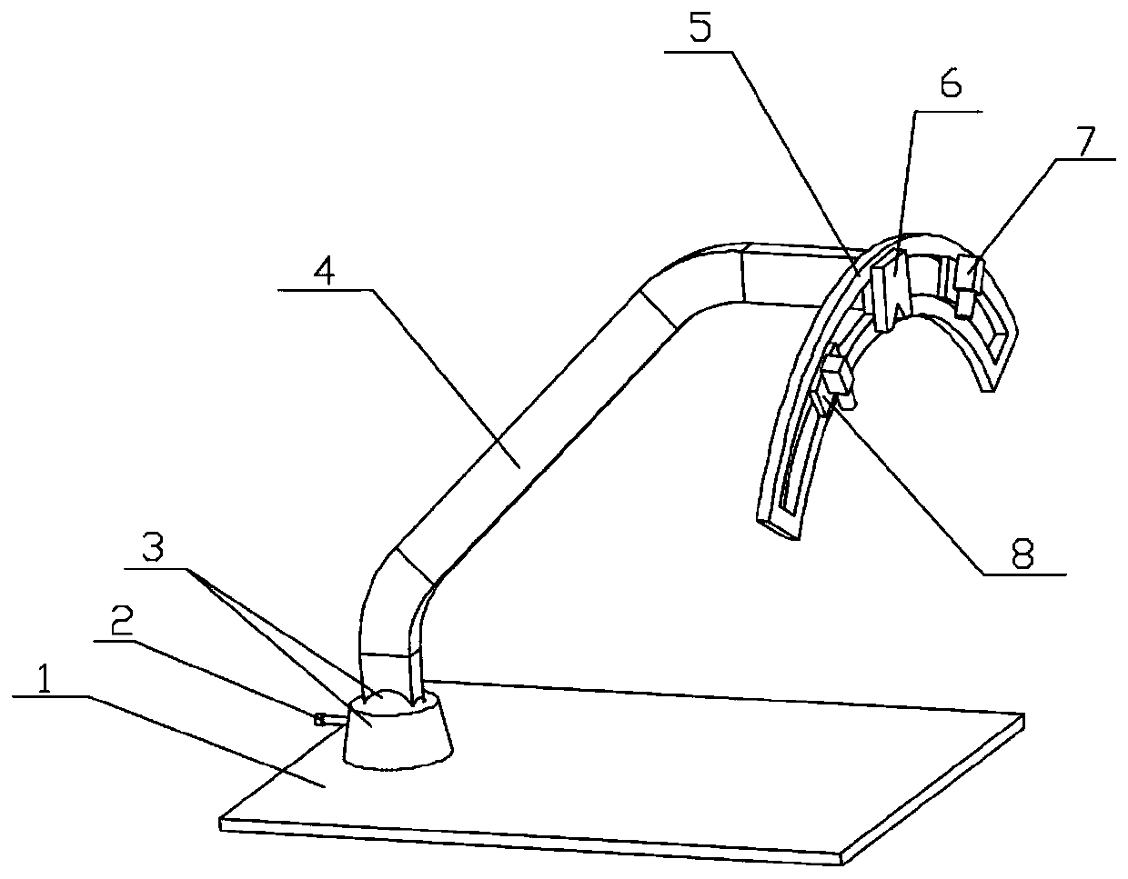
[0040] see Figure 3-6 , the embodiment of the present invention is provided with base 1, fixing bolt 2, spherical hinge 3, system bracket 4, arc frame 5, slider 8, camera 7 and laser displacement sensor 6; Said laser displacement sensor 6, camera 7 and slider Block 8 is fixed on the arc frame 5, the upper end of the system support 4 is fixed on the arc frame 5, the bottom end of the system support 4 is fixed on the base 1, and the bottom end of the system support 4 is connected with the fixing bolt 2 by a spherical hinge 3, The fixing bolt 2 is fixed on the base 1; the camera 7 is fixed on the slider 8, and the angle of the camera 7 can be adjusted on the arc-shaped frame 5.

[0041] When performing camera calibration, the laser displacement sensor measures the distance of the feature point, denoted as s, and the angle λ between the laser displaceme...


PUM


Abstract

The invention relates to the machine vision system, particularly to a visual system with laser ranging for calibration optimization. The system is provided with a base, a spherical hinge, a system bracket, an arc holder, a sliding block, a camera, and a laser displacement sensor. The laser displacement sensor, the camera, and the sliding block are fixed at the arc holder; the upper end of the system bracket is fixed at the arc holder and the bottom of the system bracket is fixed at the base; the bottom of the system bracket is connected with a fixed bolt by the spherical hinge; and the fixed bolt is fixed on the base. The camera is fixed on the sliding block and is capable of carrying out angle adjustment at the arc holder. On the basis of the design of the arc holder and the sliding block, the shooting angle of the camera can be adjusted; and conversion between data measured by the laser displacement sensor and camera data is realized.

Description

technical field [0001] The present invention relates to a machine vision system, in particular to a laser ranging optimal calibration vision system that utilizes a laser sensor to measure the distance between an image sensor and a measured object to achieve an optimal calibration process, and adjusts the position of the image sensor in time according to the calculation situation. system. Background technique [0002] The basic principle of multi-eye stereo imaging is to use multiple cameras with different angles to shoot the same object at the same time, perform pixel matching in the obtained multiple images, and obtain the coordinate relationship according to the coordinate relationship obtained by camera calibration. Depth information (ie, three-dimensional coordinates) of each pixel, thereby obtaining a three-dimensional stereoscopic image. Therefore, the most important step in stereo reconstruction is to calibrate the camera to determine the internal parameters and exte...

Claims


Application Information

Patent Timeline
Patent Type & Authority Patents(China)
IPC IPC(8): G01B11/00
CPCG01B11/00
Inventor 杨平史维程郭隐彪
Owner XIAMEN UNIV
Why Eureka
Try Eureka