
Drawer type circuit breaker busbar electrical connection structure

A drawer-type circuit breaker and electrical connection structure technology, applied in the direction of protective switch terminals/connections, switchgear components, etc., can solve the problems of complex electrical connection structure, troublesome assembly, low reliability, etc. The effect of reliable connection and simplified electrical connection structure

Inactive Publication Date: 2017-05-24
SHANGHAI LIANGXIN ELECTRICAL
View PDF7 Cites 1 Cited by
  • Summary
  • Abstract
  • Description
  • Claims
  • Application Information

AI Technical Summary

Problems solved by technology

[0004] The purpose of the present invention is to provide a drawer-type circuit breaker busbar electrical connection structure for the technical defects of the above-mentioned existing electrical connection structure with complex structure, low reliability and troublesome assembly. Each contact piece can operate independently, which simplifies the electrical connection. The structure makes the connection between the body busbar and the main circuit of the power supply system more reliable and easy to assemble

Method used


Image

  • Drawer type circuit breaker busbar electrical connection structure
  • Drawer type circuit breaker busbar electrical connection structure
  • Drawer type circuit breaker busbar electrical connection structure

Examples


Embodiment 1

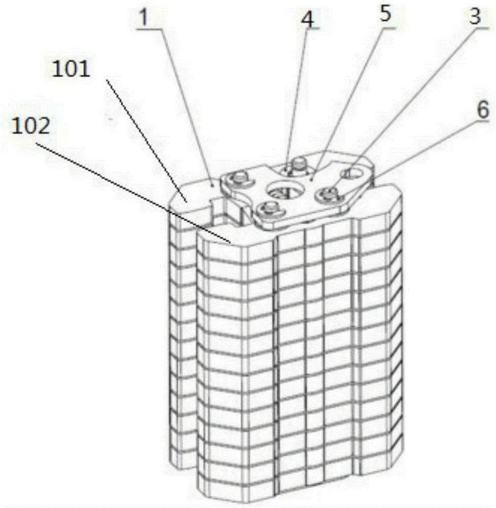
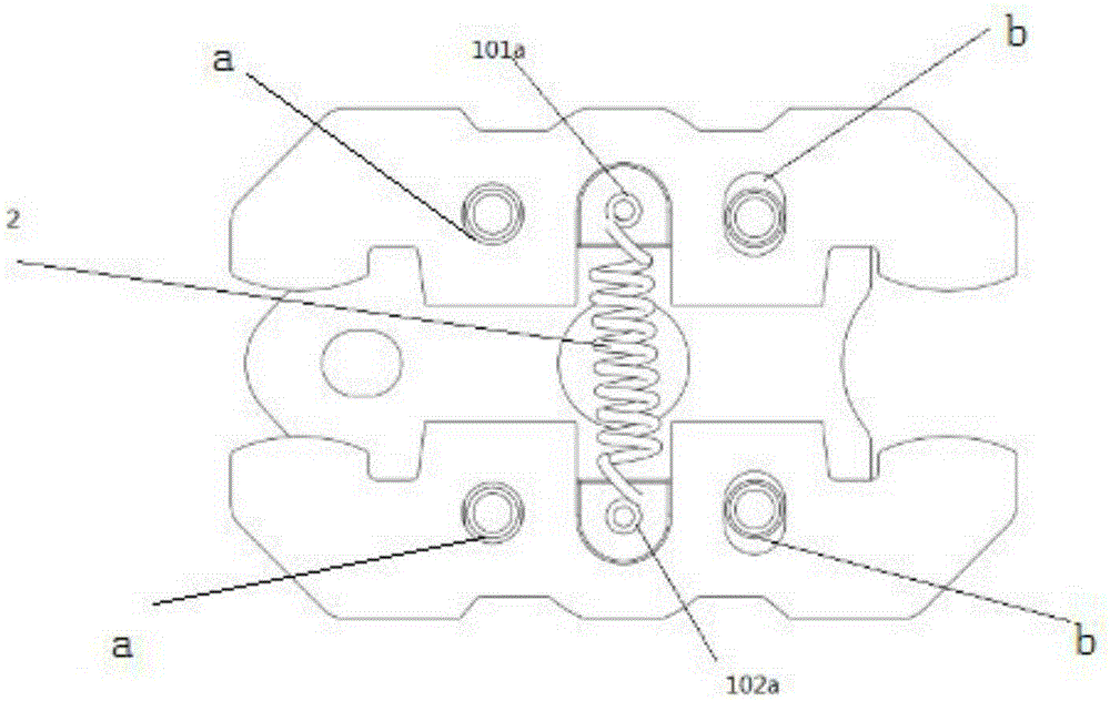
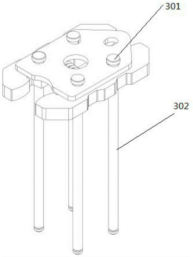
[0027] as attached figure 1 , 2 , 3, 4 and 5, a drawer-type circuit breaker busbar electrical connection structure, which includes a number of bridge-type contact piece sets 1, and the bridge-type contact piece set 1 includes an opposite left contact piece 101 and the right contact piece 102, the left contact piece 101 and the right contact piece 102 are connected by a spring 2, and several bridge-type contact piece contact groups 1 are passed through by the pin shaft 3 to be connected in series, and the bridge-type contact pieces connected in series The two ends of the head contact piece group 1 are provided with splints 5, and the splint 5 is installed on the pin shaft 3 to limit the degree of freedom along the axial direction of the pin shaft 3 through the retaining ring 6. The left contact piece 101 and the right contact piece 102 can at least move along the spring 2 movement direction movement.

[0028] Preferably, the left contact piece 101 and the right contact piece ...

Embodiment 2

[0034] as attached Image 6 and 7 As shown, the left contact piece 101 and the right contact piece 102 are respectively symmetrically arranged with at least one set of two waist-shaped holes b for positioning 0 , b", the pin shaft 3 passes through the waist hole b 0 , b", on the splint 5 and the waist-shaped hole b 0 , b" is correspondingly provided with a splint round hole b"'.

[0035] as attached Figure 8 and 9 As shown, the opposite contact surfaces of the left contact piece 101 and the right contact piece 102 of the contact piece set 1 are set as limiting structures capable of engaging with each other. Preferably, the limiting structure includes a first plane (1011), a second plane (1014), a first slope (1012), a second slope (1013), a third plane (1011'), a fourth plane (1014 '), the third inclined plane (1012'), the fourth inclined plane (1013'), the two oppositely arranged contact pieces, the first plane (1011) of one contact piece corresponds to the third plane...

Embodiment 3

[0037] The left installation part 101a and the right installation part 102a are grooves.

[0038] In the electrical connection structure of the drawer-type circuit breaker busbar provided by the present invention, each contact piece can act independently, which simplifies the electrical connection structure, does not require special assembly fixtures and tools, greatly reduces the difficulty of assembly, and makes the connection between the main body busbar and the main circuit of the power supply system The connection is more reliable.


PUM


Abstract

The invention provides a drawer type circuit breaker busbar electrical connection structure. The drawer type circuit breaker busbar electrical connection structure is characterized in that the drawer type circuit breaker busbar electrical connection structure comprises a plurality of bridge type contact contact piece groups (1). Each of the bridge type contact contact piece groups (1) comprises oppositely arranged left contact piece (101) and right contact piece (102). The left contact piece (101) and right contact piece (102) are connected through a spring (2). A pin (3) passes through the bridge type contact contact piece groups (1) to allow the bridge type contact contact piece groups (1) to be connected in series. Two ends of the bridge type contact contact piece groups (1) connected in series are provided with clamp plates (5), and the clamp plates (5) are installed on the pin (3) and are limited through retaining rings (6). According to the drawer type circuit breaker busbar electrical connection structure, each contact piece can act independently, an electrical connection structure is simplified, special assembly clamp and tool are needed, the assembly difficulty is greatly reduced, and thus the connection between a body busbar and a power supply system main loop is more reliable.

Description

technical field [0001] The invention belongs to the technical field of circuit breakers, and specifically relates to a drawer seat of a drawer type circuit breaker, which serves as a busbar electrical connection structure connecting the busbar of the body and the main circuit of the power supply system, so that the main circuit system of the power supply and the circuit breaker circuit system are safe and secure. Reliable and stable connection together. Background technique [0002] Circuit breakers are divided into high-voltage circuit breakers and low-voltage circuit breakers according to their scope of use. Low-voltage circuit breaker, also known as automatic switch, commonly known as "air switch", also refers to low-voltage circuit breaker. It is an electrical appliance that not only has the function of manual switch, but also can automatically protect against voltage loss, undervoltage, overload, and short circuit. It can be used to distribute electric energy, start as...

Claims


Application Information

Patent Timeline
Patent Type & Authority Applications(China)
IPC IPC(8): H01H71/08H02B11/04
CPCH01H71/08H02B11/04
Inventor 蒋武山
Owner SHANGHAI LIANGXIN ELECTRICAL
Learn More