
Transformer electrical cabinet

A technology for electrical cabinets and transformers, which is applied to the cooling/ventilation of transformer/inductor housings, substation/power distribution device housings, substation/switching devices, etc., and can solve the problem of poor thermal effect of transformer electrical cabinet fans and affect the safety of electrical cabinets Performance, transformer insulation aging and other issues, to avoid messy placement of wires, excellent ventilation, and good results

Inactive Publication Date: 2017-05-24
CHONGQING NARI BORUI TRANSFORMER CO LTD
View PDF0 Cites 1 Cited by
  • Summary
  • Abstract
  • Description
  • Claims
  • Application Information

AI Technical Summary

Problems solved by technology

[0002] The electrical components in the transformer electrical cabinet often generate a lot of heat due to the work of the electric load during work. The heat generated can easily cause the insulation of the transformer to age and the work efficiency to decrease. When the heat generated exceeds the heat resistance level of the transformer Finally, it is very easy to cause the transformer to be damaged due to high temperature. Therefore, the heat effect of the transformer electrical cabinet fan currently used is not good, and accidents often occur due to high temperature damage. Moreover, the transformer-related electrical components in the transformer electrical cabinet (such as control circuit boards, Air switch, terminal block, etc.) are placed in a mess, which affects the safety performance of the electrical cabinet

Method used


Image

  • Transformer electrical cabinet
  • Transformer electrical cabinet
  • Transformer electrical cabinet

Examples


Embodiment Construction

[0013] The following will clearly and completely describe the technical solutions in the embodiments of the present invention with reference to the accompanying drawings in the embodiments of the present invention. Obviously, the described embodiments are only some, not all, embodiments of the present invention. Based on the embodiments of the present invention, all other embodiments obtained by persons of ordinary skill in the art without making creative efforts belong to the protection scope of the present invention.

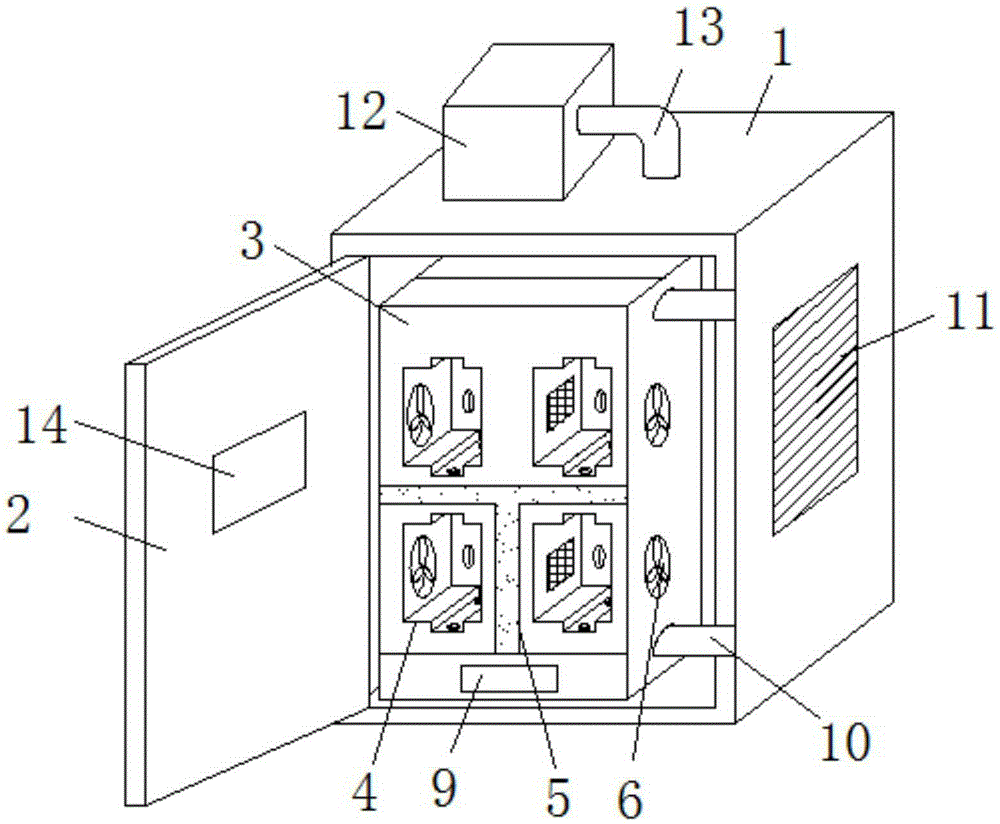
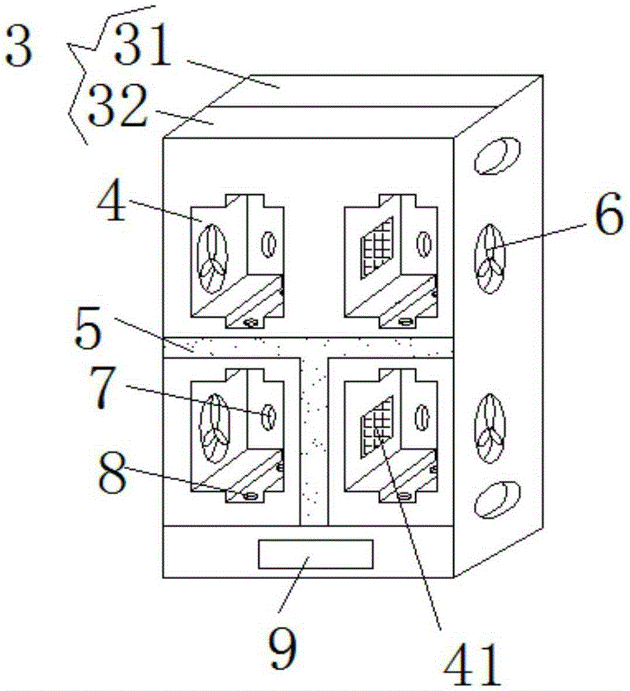
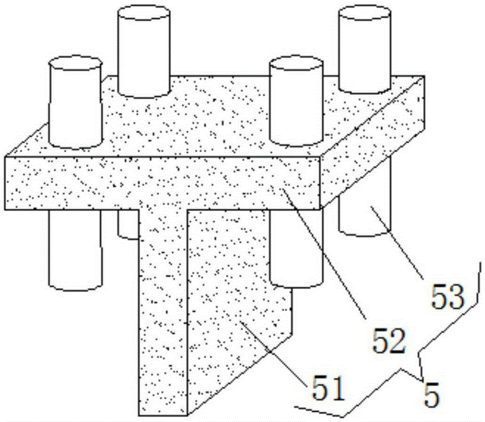
[0014] see Figure 1-3 , the present invention provides a technical solution: a transformer electrical cabinet, including a main body 1, a cabinet door 2, an electrical installation device 3 and an air induction device 5, the side of the main body 1 is provided with a grid plate 11, and the front end of the main body 1 passes through The rotating shaft is hinged with the cabinet door 2, and a controller 14 is installed in the inner cavity of the cabinet door 2...


PUM


Abstract

The invention discloses a transformer electrical cabinet. The transformer electrical cabinet comprises a body, a cabinet door, an electrical appliance mounting device and an air intake device, wherein the top portion of the body is provided with a drawing fan, a chamber of the body is fixedly connected with the electrical appliance mounting device through a fixing shaft, a side surface of the electrical appliance mounting device is provided with an exhaust fan, the electrical appliance mounting device comprises a wire chamber and a mounting chamber, the top portion of the mounting chamber is connected with a tail end of an exhaust pipe, the middle portion of the chamber of the mounting chamber is provided with the air intake device, the bottom portion of the air intake device is connected with a blower, the air intake device comprises a vertical channel, a transverse channel and a connection pipe, and the upper portion and the lower portion of the chamber of the mounting chamber are respectively provided with a mounting groove. The transformer electrical cabinet is advantaged in that ventilation for each mounting groove is carried out through the air intake device, the exhaust fan and the drawing fan, high radiation efficiency and good radiation effect are realized, the structure is simple, the transformer electrical cabinet is convenient to use, electrical appliances can be neatly and orderly placed, excellent ventilation is realized, the structure is ingenious, and strong practicality is realized.

Description

technical field [0001] The invention relates to the technical field of power equipment, in particular to a transformer electrical cabinet. Background technique [0002] The electrical components in the transformer electrical cabinet often generate a lot of heat due to the work of the electric load during work. The heat generated can easily cause the insulation of the transformer to age and the work efficiency to decrease. When the heat generated exceeds the heat resistance level of the transformer Finally, it is very easy to cause the transformer to be damaged due to high temperature. Therefore, the heat effect of the transformer electrical cabinet fan currently used is not good, and accidents often occur due to high temperature damage. Moreover, the transformer-related electrical components in the transformer electrical cabinet (such as control circuit boards, Air switches, terminal blocks, etc.) are also placed in a mess, which affects the safety performance of the electri...

Claims


Application Information

Patent Timeline
Patent Type & Authority Applications(China)
IPC IPC(8): H02B1/26H02B1/56H01F27/02
Inventor 张广明
Owner CHONGQING NARI BORUI TRANSFORMER CO LTD
Learn More