
Charging and discharging module and electronic device

A charge-discharge and module technology, which is applied to battery circuit devices, collectors, electric vehicles, etc., can solve the problems of long discharge path, large discharge loss, and small plates can only be placed with protectors, so as to shorten the discharge path and reduce the Effect of Discharge Path Loss

Inactive Publication Date: 2017-05-24
林则峰
View PDF6 Cites 0 Cited by
  • Summary
  • Abstract
  • Description
  • Claims
  • Application Information

AI Technical Summary

Problems solved by technology

On the one hand, the discharge path of traditional mobile phones is long, and the discharge loss is large; on the other hand, the small board of traditional mobile phones can only place protectors, charging ports, etc., which limits the layout of mobile phones to a certain extent.

Method used


Image

  • Charging and discharging module and electronic device
  • Charging and discharging module and electronic device
  • Charging and discharging module and electronic device

Examples


Embodiment Construction

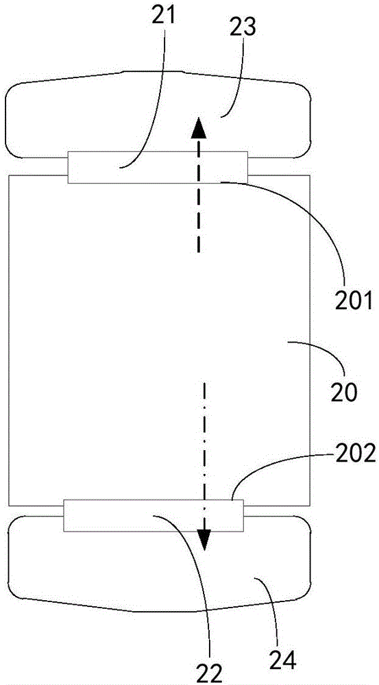
[0020] see figure 2 , figure 2 It is a structural schematic diagram of an embodiment of the charging and discharging module of the present invention, including:

[0021] The battery cell 20, the positive and negative tabs of the battery cell 20 are respectively drawn from both ends to form a first interface 201 and a second interface 202;

[0022] The first protection board 21 and the second protection board 22, one end of the first protection board 21 and the second protection board 22 are respectively coupled with the first interface 201 and the second interface 202; The position of the protection board 22 also includes a connector, figure 2 not indicated in

[0023] The first main board 23 and the second main board 24 are respectively coupled with the other end of the first protection board 21 and the second protection board 22; shown) coupling.

[0024] Wherein, the first interface 201 and the second interface 202 of the battery cell 20 are arranged adjacent to the...


PUM


Abstract

The invention discloses a charging and discharging module and an electronic device. The charging and discharging module comprises an electric core, a first protection plate, a second protection plate, a first mainboard and a second mainboard, and is characterized in that the electric core comprises a first interface and a second interface; one end of the first protection plate and one end of the second protection plate are respectively coupled to the first interface and the second interface; and the first mainboard and the second mainboard are respectively coupled to the other end of the first protection plate and the other end of the second protection plate. A first discharging path and a second discharging path are defined, wherein the first discharging path comprises that the first interface of the electric core generates first discharging current, the first discharging current flows to the first mainboard through the first protection plate, and the first mainboard is coupled to a load; and the second discharging path comprises that the second interface of the electric core generates second discharging current, the second discharging current flows to the second mainboard through the second protection plate, and the second mainboard is coupled to the load. The loss of the discharging paths can be effectively reduced according to the mode disclosed by the invention.

Description

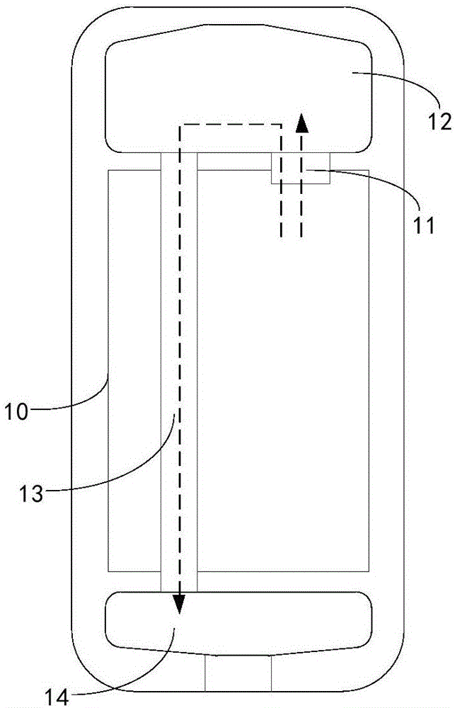
technical field [0001] The invention relates to the technical field of charge and discharge, in particular to a charge and discharge module and electronic equipment. Background technique [0002] At present, large-screen mobile phones are becoming more and more popular, and the length and width of mobile phones are getting larger and larger, which makes the length of the discharge path designed by traditional mobile phones increase accordingly, and the loss consumed in the discharge path will also increase. Traditional mobile phone design methods such as figure 1 As shown, the positive and negative tabs of the battery cell 10 are drawn from one end and connected to the protection board 11. The path of the mobile phone during discharge includes: battery cell 10-protection board 11-main board 12 and battery cell 10-protection board 11-main board 12 - flexible circuit board 13 - small board 14 . On the one hand, the discharge path of traditional mobile phones is long, and the...

Claims


Application Information

Patent Timeline
Patent Type & Authority Applications(China)
IPC IPC(8): H02J7/00
CPCH02J7/0042
Inventor 李城铭倪漫利
Owner 林则峰
Learn More