Ignition apparatus

a technology of ignition apparatus and discharge path, which is applied in the direction of spark gap circuit, automatic control of ignition, machines/engines, etc., can solve the problems of variable output torque of the engine, variable discharge path length, and constant discharge of the discharged spark, so as to reduce the drive current of the ignition plug, shorten the discharge path, and increase the impedance of the discharge

Active Publication Date: 2019-04-02
DENSO CORP
View PDF24 Cites 0 Cited by
  • Summary
  • Abstract
  • Description
  • Claims
  • Application Information

AI Technical Summary

Benefits of technology

[0007]According to an exemplary embodiment, there is provided an ignition apparatus which includes an ignition plug, a boost transformer, an ignition power source and a measurement unit. The ignition plug has a center electrode and a ground electrode to produce a discharge therebetween upon being supplied with electric power. The boost transformer has a primary coil and a secondary coil magnetically coupled with each other. The boost transformer is configured to supply the ignition plug with the electric power that is generated in the secondary coil by electromagnetic induction upon supply of AC power to the primary coil. The ignition power source is configured to supply the primary coil of the boost transformer with the AC power. The measurement unit is configured to measure at least one of discharge voltage and discharge current of the ignition plug. The ignition power source includes a controller that has a discharge state determining unit configured to determine the discharge state of the ignition plug based on the at least one of the discharge voltage and the discharge current measured by the measurement unit and a current controlling unit configured to control electric current supplied to the primary coil of the boost transformer. The controller is configured so that when a discharge path formed between the center and ground electrodes of the ignition plug is determined by the discharge state determining unit as being in an over-extended state, the current controlling unit reduces the electric current supplied to the primary coil of the boost transformer.
[0008]With the above configuration, when the discharge path formed between the center and ground electrodes of the ignition plug is excessively extended by the flow of an air-fuel mixture in a combustion chamber, the electric current supplied to the primary coil of the boost transformer is reduced by the current controlling unit, thereby reducing drive current of the ignition plug. Moreover, with the reduction in the drive current of the ignition plug, the impedance of the discharge is increased. Forming a short circuit of the discharge and thereby shortening the discharge path is advantageous to lowering the impedance of the discharge; thus formation of a short circuit is promoted. Consequently, a short circuit of the discharge is formed within the air-fuel mixture, thereby shortening the discharge path. As a result, it becomes possible to prevent the discharge path from becoming excessively long, thereby suppressing variation in the discharge shape between each combustion cycle.

Problems solved by technology

However, the blowing of the discharged spark is not constant; therefore, there is variation in the length of the discharge path.
This may cause the output torque of the engine to vary between each combustion cycle.
Consequently, a short circuit of the discharge is formed within the air-fuel mixture, thereby shortening the discharge path.

Method used


Image

  • Ignition apparatus
  • Ignition apparatus
  • Ignition apparatus

Examples


first modification

[First Modification]

[0103]In this modification, as shown in FIG. 7, after step S13, the process performed by the controller 42 directly proceeds to step S22, omitting step S20 (see FIG. 4) described in the above embodiment. Moreover, if the determination at step S12 produces a “NO” answer, the process directly proceeds to step S19, omitting steps S14-S18 (see FIG. 4) described in the above embodiment.

second modification

[Second Modification]

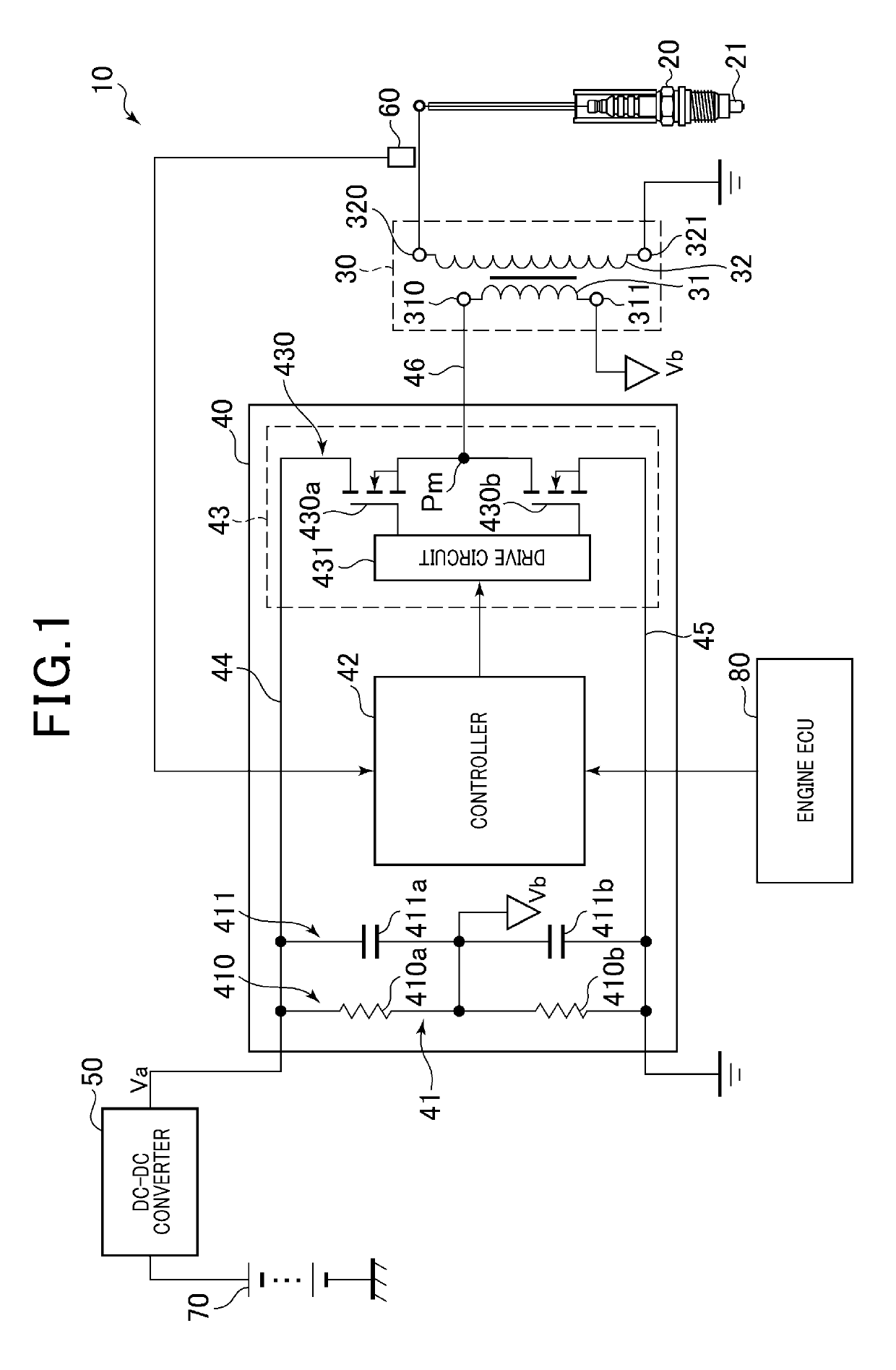
[0104]In this modification, at steps S13, S16 and S18 of the process described in the above embodiment with reference to FIG. 4, the AC current supplied to the primary coil 31 of the boost transformer 30 is adjusted by varying, instead of the voltage duty ratio, the frequency of the AC voltage applied by the ignition power source 40 to the primary coil 31 of the boost transformer 30.

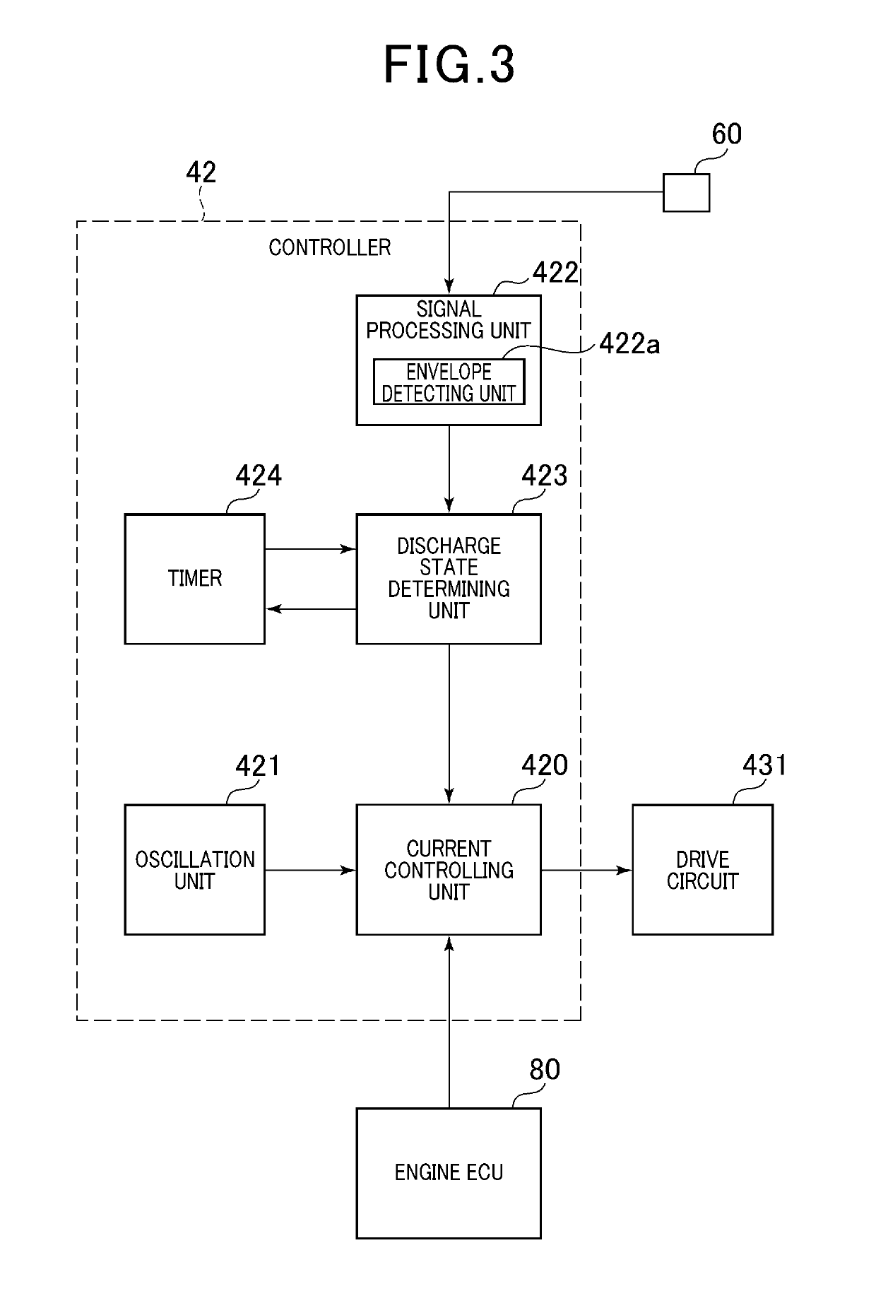
[0105]Specifically, in this modification, as shown in FIG. 8, the controller 42 includes, instead of the oscillation unit 421 described in the above embodiment with reference to FIG. 3, a variable oscillation unit 421 that is capable of varying the frequency of a carrier signal generated by it and outputted from it to the current controlling unit 420. The discharge state determining unit 423 outputs a frequency increase command signal or a frequency reduction command signal to the variable oscillation unit 421, thereby causing the variable oscillation unit 421 to raise or lower the f...

third modification

[Third Modification]

[0106]In this modification, at steps S13, S16 and S18 of the process described in the above embodiment with reference to FIG. 4, the AC current supplied to the primary coil 31 of the boost transformer 30 is adjusted by varying, instead of the voltage duty ratio, the DC voltage applied by the DC-DC converter 50 to the ignition power source 40.

[0107]Specifically, in this modification, as shown in FIG. 9, the discharge state determining unit 423 outputs a voltage increase command signal or a voltage reduction command signal to the DC-DC converter 50, thereby causing the DC-DC converter 50 to raise or lower the DC voltage applied to the ignition power source 40.


PUM

PropertyMeasurementUnit
DC voltageaaaaaaaaaa
frequencyaaaaaaaaaa
discharge-sustaining voltageaaaaaaaaaa

Abstract

An ignition apparatus includes an ignition plug, a boost transformer, an ignition power source and a measurement unit. The ignition plug has a center electrode and a ground electrode. The boost transformer supplies the ignition plug with electric power generated in a secondary coil upon supply of AC power from the ignition power source to a primary coil. The measurement unit measures the discharge voltage of the ignition plug. The ignition power source includes a discharge state determining unit that determines the discharge state of the ignition plug based on the measured discharge voltage and a current controlling unit that controls electric current supplied to the primary coil. When a discharge path formed between the center and ground electrodes of the ignition plug is determined by the discharge state determining unit as being in an over-extended state, the current controlling unit reduces the electric current supplied to the primary coil.

Description

CROSS-REFERENCE TO RELATED APPLICATION[0001]This application is based on and claims priority from Japanese Patent Application No. 2016-172216 filed on Sep. 2, 2016, the content of which is hereby incorporated by reference in its entirety into this application.BACKGROUND1 Technical Field[0002]The present invention relates to ignition apparatuses for use in engines.2 Description of Related Art[0003]Japanese Patent No. JP5676721B1 discloses an ignition apparatus for use in an engine. The ignition apparatus includes a spark discharge producing device, a resonance device, a current supply device, a current level detection device and a control device. The spark discharge producing device generates a predetermined high voltage and supplies the generated predetermined high voltage to an ignition plug, thereby forming a spark discharge path in a gap of the ignition plug. The resonance device is composed of an inductor and a capacitor. The current supply device supplies, via the resonance dev...

Claims


Application Information

Patent Timeline
Patent Type & Authority Patents(United States)
IPC IPC(8): F02P3/055F02P17/02H01T15/00H01F38/12F02P3/01F02P3/00F02P9/00F02P5/15F02P17/12
CPCF02P3/055F02P3/005F02P3/01F02P9/002H01F38/12H01T15/00F02P17/02F02P2017/121F02P5/1502
Inventor KINOSHITA, SHOTAAOKI, FUMIAKISUGIURA, AKIMITSUDOI, KAORI
Owner DENSO CORP
Why Eureka
Try Eureka