Live video matching method and system

A video and synthesizer technology, applied in the field of live video media, can solve problems such as high delay and insufficient bandwidth, and achieve the effect of solving bottlenecks, reducing delay, and shortening transmission paths

Active Publication Date: 2017-05-24
NANNING FUGUI PRECISION IND CO LTD
View PDF7 Cites 0 Cited by
  • Summary
  • Abstract
  • Description
  • Claims
  • Application Information

AI Technical Summary

Problems solved by technology

In this way, although many users can be served, the delay will be high
In addition

Method used


Image

  • Live video matching method and system
  • Live video matching method and system
  • Live video matching method and system

Examples


Embodiment Construction

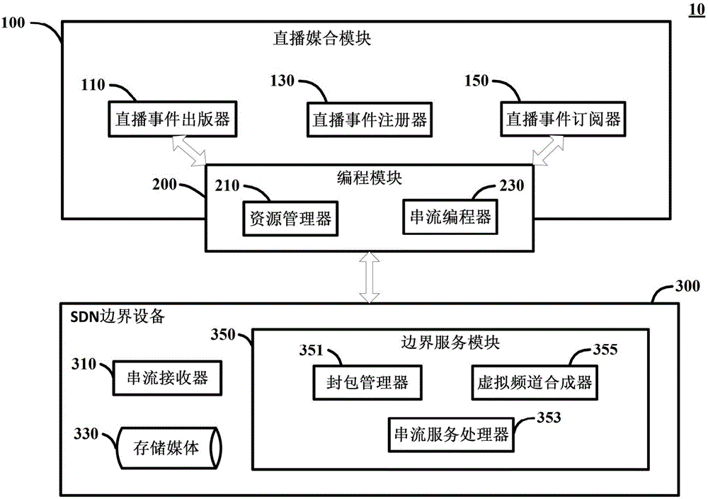
[0051] The live video matchmaking method and system of the embodiment of the present invention are characterized in that:

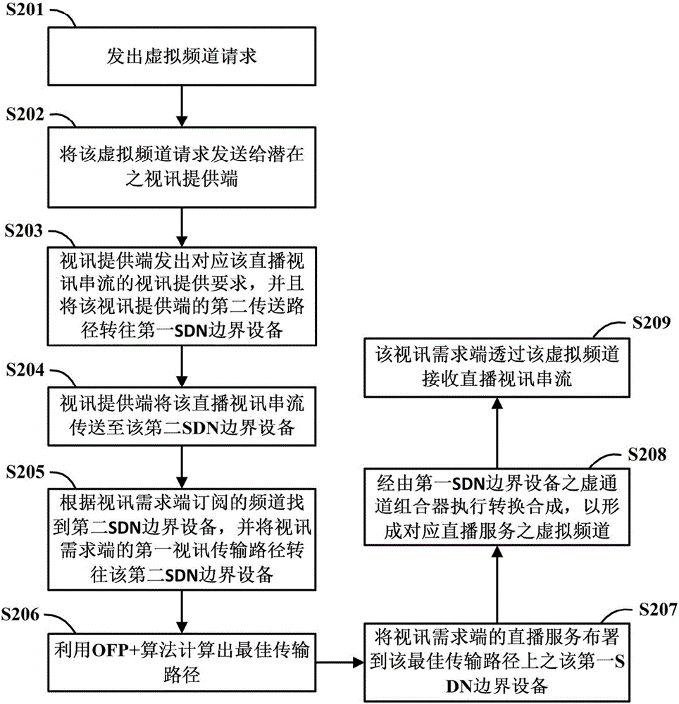
[0052] (1) By matching the video demand side with the video provider, provide the video demand side to watch the live broadcast service. That is to say, the video requester sends a channel request (Channel Request), and after receiving the channel request, the video provider transmits the relevant video stream to the SDN network. Therefore, the video requester can select and watch video streams in the network.

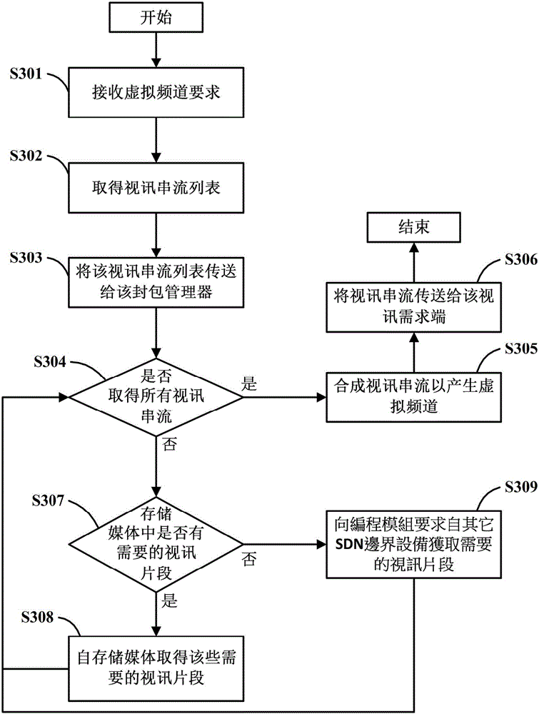
[0053] (2) The SDN device at the network edge (Edge) converts and synthesizes the video stream in the SDN network according to the selection of the video demand side to form a virtual channel (Virtual Channel) to provide live broadcast services.

[0054] (3) According to the real-time available resources of the network and the load capacity of each node, an improved optimized forwarding path (Optimized Forwarding Path, OFP) algorithm (that is, OF...


PUM


Abstract

Disclosed is a live video matching system. A live matching module of the system provides a matching service between a video demander and a video provider. A programming module of the system dynamically adjusts live services provided by software-defined networking (SDN) edge devices according to network available resources in real time. An SDN edge device of the system dynamically converts multiple video streams to generate a virtual channel based on results of matching within multiple requests and provides flexible live video channel services.

Description

technical field [0001] The present invention relates to a live video matchmaking method and system based on Software-Defined Networking (SDN). Background technique [0002] Network transmission technology is changing with each passing day, and the network bandwidth provided by Internet Service Providers (Internet Service Providers, ISPs) is getting larger and larger, so everyone can act as a video provider. Compared with traditional live broadcast (Live) applications, the amount of uploaded video data is quite huge, but the network bandwidth cannot be expanded without limit, so the upload bandwidth will become a bottleneck. [0003] Known technologies include using a peer-to-peer (Peer-to-Peer, P2P) communication architecture and a client-server (Client-Server) architecture to achieve the purpose of webcasting. [0004] The P2P communication architecture can make the delay (Latency) smaller. However, when the number of clients increases, the load of each node in the mesh n...

Claims


Application Information

Patent Timeline
IPC IPC(8): H04N21/2187H04N21/24H04N21/442H04N21/845
CPCH04N21/2187H04N21/2402H04N21/44227H04N21/44245H04N21/8456H04N21/222H04N21/238H04N21/2668H04N21/632H04N21/2385H04N21/2393H04N21/64738
Inventor 林士能林冠宏李吉峰
Owner NANNING FUGUI PRECISION IND CO LTD
Why Eureka
Try Eureka