Welding strain gauge curing device and process

A welding strain and curing device technology, applied in the direction of connecting components, mechanical equipment, etc., can solve the problems of no clear operating instruments and methods, and achieve the effects of improving measurement performance, convenient use, and improving specifications and standardization

Pending Publication Date: 2022-07-29
GUANGXI UNIV
View PDF0 Cites 0 Cited by
  • Summary
  • Abstract
  • Description
  • Claims
  • Application Information

AI Technical Summary

Problems solved by technology

The existing welding strain gauge manufacturing process has no clear operating instruments and methods for the pressure curing process

Method used


Image

  • Welding strain gauge curing device and process
  • Welding strain gauge curing device and process
  • Welding strain gauge curing device and process

Examples


Embodiment 1

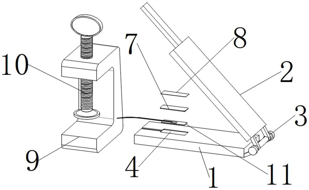
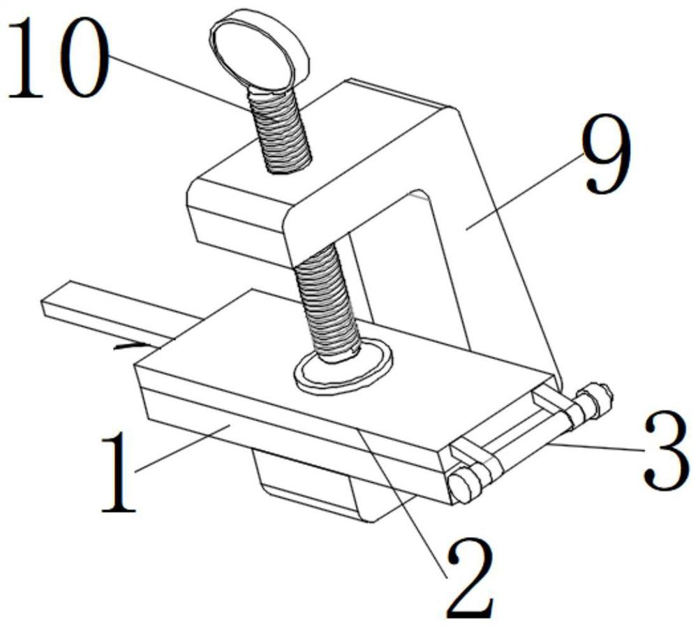
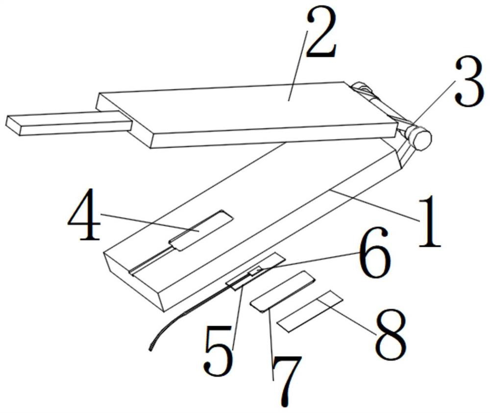
[0033] like Figure 1-3 As shown in the figure, the embodiment of the present invention provides a welding strain gauge curing device, including a welding strain gauge clamping template and a pressure pedestal. Rotating around the axis, it is very convenient to open and close, so that the lower bottom plate 1 and the upper top plate 2 fit tightly when they are attached. The size of 4 is consistent with the size of the welding strain gauge 11, and grooves 4 of different sizes and shapes can be engraved on the same lower bottom plate 1. The groove 4 is processed by the engraving process, and the welding strain gauge 11 is placed inside the groove 4. , the welding strain gauge 11 includes a thin stainless steel substrate 5, a resistance strain gauge sensing element 6, and the resistance strain gauge sensing element 6 is fixed and connected to the thin stainless steel substrate 5 by a long-term high-performance two-component epoxy resin adhesive H-610 , the upper surface of the w...

Embodiment 2

[0036] The key to the pressure curing process is the reasonable control of pressure, temperature and time.

[0037] The welding strain gage curing process includes the following steps:

[0038] S1. Placement

[0039] Paste the resistance strain gauge sensing element 6 on the thin stainless steel substrate 5, place the preliminarily bonded thin stainless steel substrate 5 and the resistance strain gauge sensing element 6 in the groove 4, and place a layer of polytetrafluoroethylene on the top. Film 7, then install the plastic groove substrate 8, and attach the lower bottom plate 1 and the upper top plate 2, and place them on the U-shaped platform 9;

[0040] S2. Perform initial solidification

[0041] By rotating the pressurizing threaded rod 10, the pressure is increased to make the pressure reach 0.1-0.3MPa, and then the device is put into a temperature box, the temperature is 120 ° C, and the temperature is kept for two hours;

[0042] S3. Subsequent processing

[0043] ...


PUM


Abstract

The invention provides a welding strain gauge curing device and process, and relates to the field of sensor processing. The welding strain gauge curing device comprises a welding strain machine clamping template and a pressurizing pedestal, the clamping template is formed by connecting a lower bottom plate and an upper top plate through a rotating bearing, a groove is formed in the upper surface of the lower bottom plate, a welding strain gauge is placed in the groove, the pressurizing pedestal comprises a U-shaped bearing platform and a pressurizing threaded rod, and the U-shaped bearing platform is connected with the pressurizing threaded rod through a screw. And the pressurizing threaded rod is in threaded connection with the U-shaped bearing platform. The invention provides a key process in the manufacturing process of the welding strain gauge and an instrument required by the key process, and the welding strain gauge is simple in structure, easy to process and manufacture, convenient to use and suitable for production in laboratories and enterprise plants. According to the instrument and the process, the bottleneck link in the manufacturing of the welding strain gauge is solved, the specification and standardization of the production process of the welding strain gauge are favorably improved, the quality of the welding strain gauge and the measurement performance during application are improved, and the wide application of the welding strain gauge is promoted.

Description

technical field [0001] The invention relates to the technical field of sensor processing, in particular to a welding strain gauge curing device and process. Background technique [0002] Welded strain gauges are essentially a resistance strain gauge. Traditional resistance strain gauges are pasted on a thin stainless steel substrate of suitable size, so that the strain gauge has the characteristics of welding. Steel beams, steel columns, steel truss members and metal machines, etc. Welded strain gauges have the same temperature performance self-compensation and consistency as ordinary resistance strain gauges. Compared with ordinary resistance strain gauges, they have the disadvantages of cumbersome process, low efficiency, and limited by the construction site environment. They have spot welding installation. The advantages of flexible layout of instant welding and measuring, and the protection and fixing of the lead wires are carried out to ensure that the lead wires are f...

Claims


Application Information

Patent Timeline
Patent Type & Authority Applications(China)
IPC IPC(8): F16B11/00
CPCF16B11/006
Inventor 邓年春段吉强
Owner GUANGXI UNIV
Why Eureka
Try Eureka