Monitoring method for aligning degree of laser drilling

A technology of laser drilling and alignment, applied in circuit inspection/monitoring/correction, printed circuits, electrical components, etc., can solve the problems of selection, leakage, and low efficiency that cannot be laser drilled and drilled

Inactive Publication Date: 2017-05-24
AOSHIKANG TECH CO LTD
View PDF1 Cites 7 Cited by
  • Summary
  • Abstract
  • Description
  • Claims
  • Application Information

AI Technical Summary

Problems solved by technology

[0004] 1. Magnifying glass detection: Random detection of personnel, low efficiency and high possibility of leakage;
[0005] 2. AOI detection: through optical reflection principle detection, due to the impact of machine parameter...

Method used


Image

  • Monitoring method for aligning degree of laser drilling
  • Monitoring method for aligning degree of laser drilling
  • Monitoring method for aligning degree of laser drilling

Examples


Embodiment

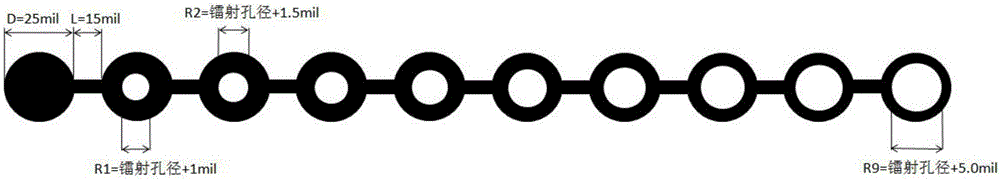
[0026] Design laser drilling alignment monitoring Coupon (module), such as figure 1 As shown, this module is set on the process side and has no functional impact on the contents of the board.

[0027] The module design content is as follows:

[0028] 1. In the laser drilling Target (the pad layer at the bottom of the laser drilling hole, it can also be called the bottom pad of the blind hole, with the attached Figure 5 -Laser drilling) layer design a row of series Pad*10 (such as figure 2 -Laser drilling Target layer module design), Pad size D = 25mil, distance between Pad and Pad L = 15mil, the first Pad is solid, the middle of the second Pad is etched and isolated, the isolation size R1 = laser drilling aperture + 1mil ( For example, the laser drilling aperture is 4.0mil, R1=5mil), the middle etching isolation of the third Pad, the isolation size R2=laser drilling aperture+1.5mil, the fourth Pad etching isolation in the middle, the isolation size R3=laser drilling apertu...


PUM


Abstract

The invention relates to a monitoring method for aligning degree of laser drilling. The monitoring method comprises the following steps of (1) according to the size of laser drilling Target Pad Ring, calculating the monitoring size of the aligning degree, wherein the calculation formula is monitoring of aligning degree=(Target Pad Ring-Target layer compensation)/0.5; (2) testing method: after the monitoring value of the aligning degree of the laser drilling is calculated, arranging a testing needle under an electric measuring jig to the corresponding Pad; (3) judging method: if OPEN is tested out, the aligning degree is OK; if SHORT is tested out, the aligning degree is NG. The monitoring method has the advantage that the abnormal deviation of laser drilling is efficiently and accurately verified.

Description

technical field [0001] The invention relates to the field of PCB laser drilling manufacturing quality confirmation, in particular to a method for monitoring the alignment of laser drilling. Background technique [0002] With the development of the PCB industry, HDI (High Density Interconnect) has become a mainstream product in the PCB industry. Laser drilling has become an important feature of HDI products because of its small aperture and high density. Drilling deviation has become a key defect in laser drilling. In order to better control product quality and prevent defective products from flowing to customers, all manufacturers adopt AOI inspection stations (processes) after laser drilling. [0003] In the existing laser drilling process, many companies use magnifying glasses and AOI to detect abnormalities in laser drilling: [0004] 1. Magnifying glass detection: Random detection of personnel, low efficiency and high possibility of leakage; [0005] 2. AOI detection:...

Claims


Application Information

Patent Timeline
IPC IPC(8): H05K3/00
CPCH05K3/0026H05K2203/107H05K2203/16
Inventor 张金才陈志新罗新权
Owner AOSHIKANG TECH CO LTD
Why Eureka
Try Eureka