High precision, rapid laser hole drilling

a laser hole, high-precision technology, applied in the field of laser hole drilling, can solve the problems of low drilling speed, long drilling time, low material removal rate, etc., and achieve the effect of high precision

Inactive Publication Date: 2005-03-08
LAWRENCE LIVERMORE NAT SECURITY LLC
View PDF13 Cites 35 Cited by
  • Summary
  • Abstract
  • Description
  • Claims
  • Application Information

AI Technical Summary

Benefits of technology

The present invention provides a system for drilling holes in a material. In one embodiment of the invention an apparatus includes a laser system that produces a first laser beam for rapidly removing the bulk of material in an area to form a ragged hole and a second laser beam for accurately cleaning up the ragged hole so that the final hole has dimensions of high precision. In another embodiment of the invention the first laser beam is an infra-red laser beam. The second laser beam is a low power, short wavelength laser beam.
An embodiment of the present invention provides a method producing a hole in a material using a first laser beam for rapidly removing the bulk of material in an area to form a ragged hole and a second laser beam for accurately cleaning up the ragged hole so that the final hole has dimensions of high precision. The method begins by the first laser operated in the ablative mode generating a first laser beam. The first laser beam is directed at the material where the hole is desired. The first laser beam removes the bulk of the material and begins the process of forming a hole. Subsequently a laser, operated in the trepanning mode, generates a second laser beam. The second laser beam is directed into the hole being formed to clean up the hole so that the resulting hole has dimensions of high precision.
An embodiment of the present invention provides a piece with a hole therein produced by the method of: generating a first laser beam, directing the first laser beam at the piece to remove the bulk of material in an area to form a ragged hole and begin forming the hole, generating a second laser beam, and directing the second laser beam at the hole being formed for accurately cleaning up the ragged hole so that the final hole has dimensions of high precision.
In an embodiment of the present invention provides a system for drilling a hole in a material using a laser system that produces a first laser beam for rapidly removing the bulk of material in an area to form a ragged hole and a second laser beam for accurately cleaning up the ragged hole so that the final hole has dimensions of high precision. The first laser beam is controlled so that the hole does not extend entirely through the material. A thin membrane is left at the bottom of the hole. The second laser beam breaks through the thin membrane at the bottom of the hole.

Problems solved by technology

Deep holes with high aspect ratios pose a problem because the ablative material can redeposit on the walls of the hole causing a taper or other irregularities.
The problem with conventional trepanning is that the drilling speed is low.
This is because the central plug must be heated and extracted by melting and vaporization; this process is energy intensive and therefore drilling times are long.
Too low a flux results in pure heating of the substrate with no ablation and hence low material removal rates.
Although DPSSL's of this power level do exit, their beam quality is not sufficient to produce “reasonable” quality holes, even with the trepanning step to follow.
Although this technique alone is not sufficient to produce near diffraction limited wavefronts due to the simultaneous presence of thermal lensing, the goal here is only 10-15 times diffraction limited and the polarization rotation technique will be sufficient.
However, the quality of the hole is far from the requirements specified.
Splatter and recast material make the hole irregular and tapered.
A visible laser with good beam quality operating at tens of watts could cut the hole to the level of precision desired by trepanning (see reference Chang, Warner, Dragon and Martinez, Ibid) but would require over a hundred seconds to complete because of the slow removal rate and the need to melt out the middle of the hole.
Some materials, ceramics for instance, are difficult to cut with near IR lasers.

Method used


Image

  • High precision, rapid laser hole drilling
  • High precision, rapid laser hole drilling
  • High precision, rapid laser hole drilling

Examples


Embodiment Construction

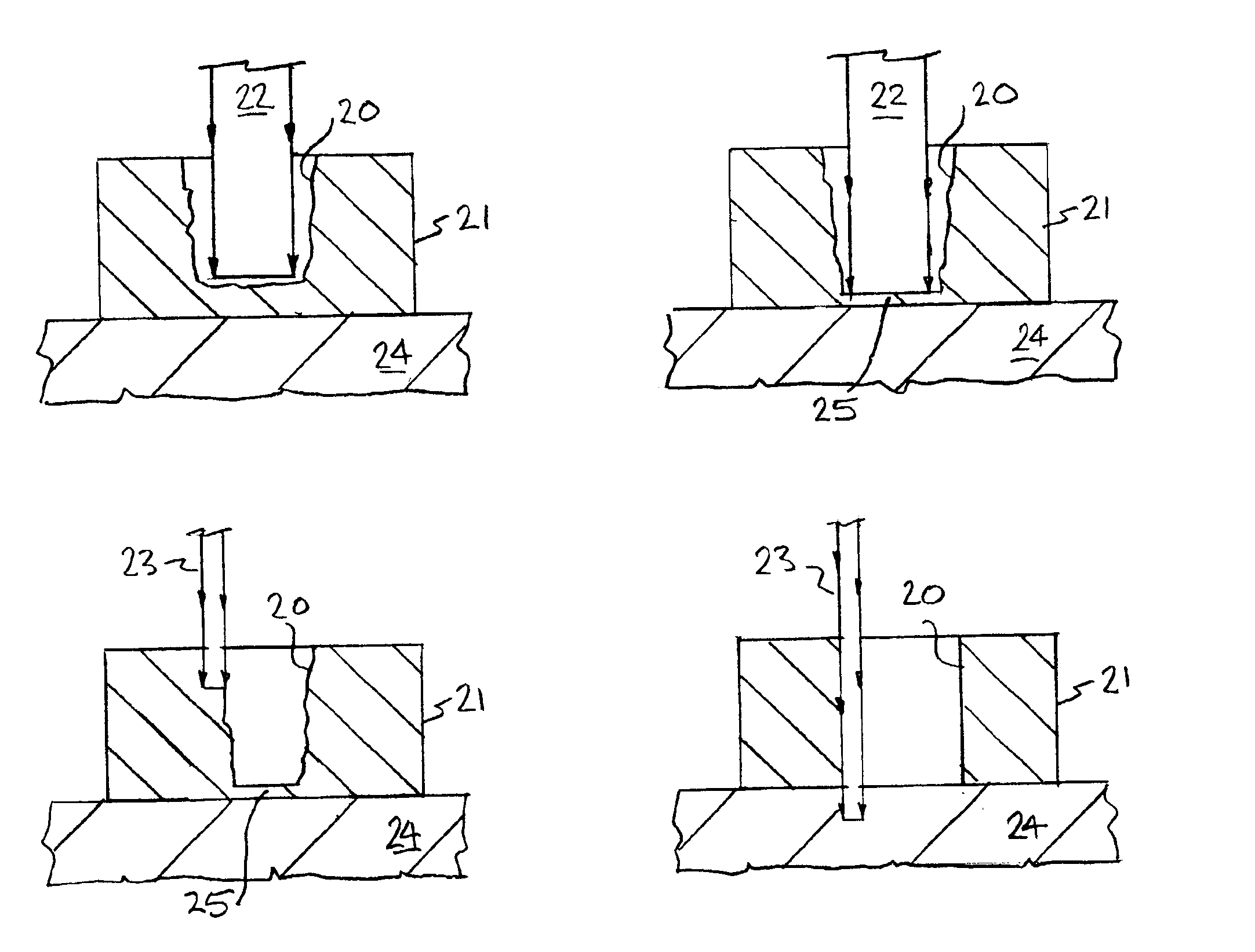
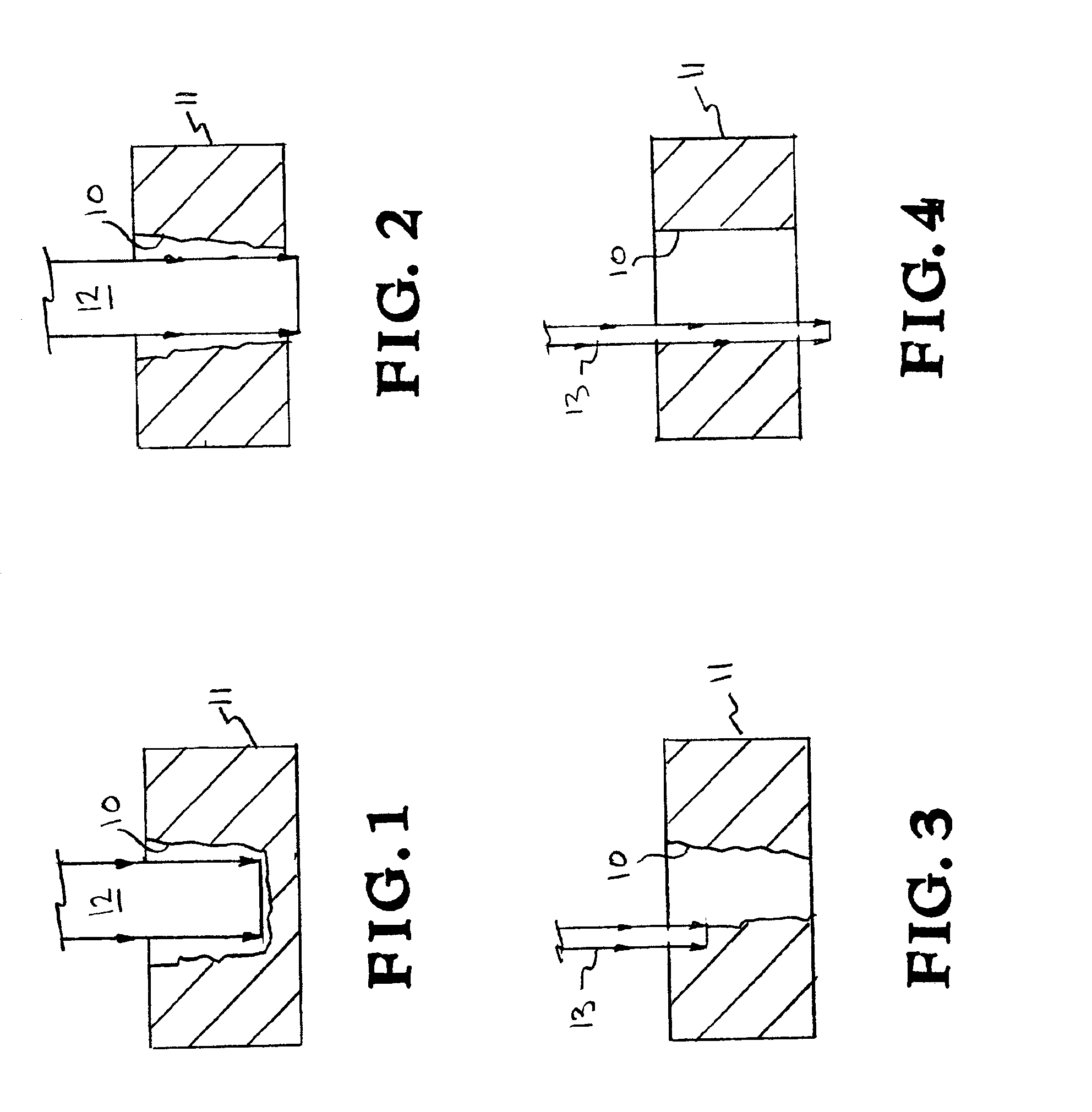
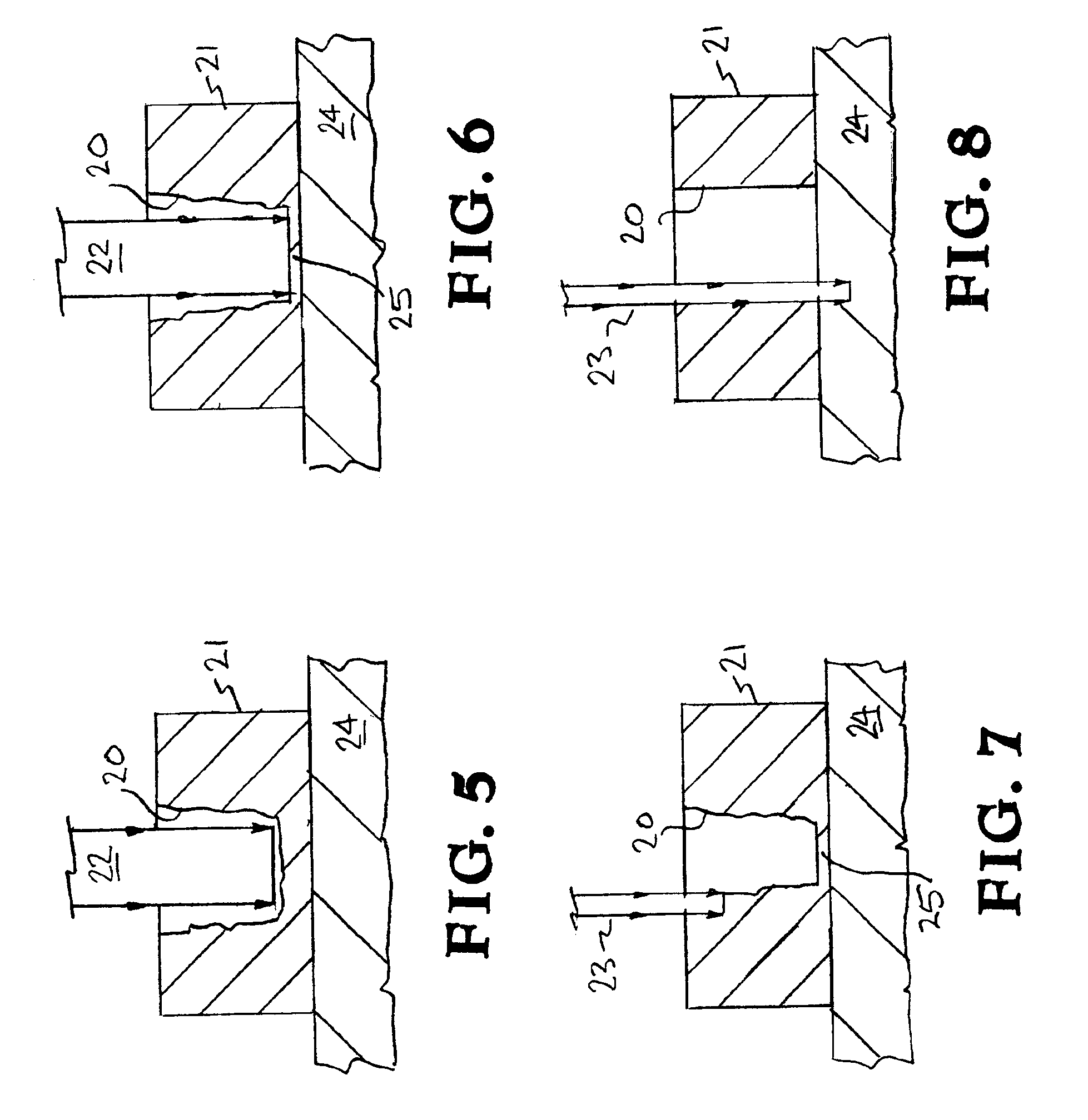
Referring now to the drawings, specific embodiments of the invention are shown. The detailed description of the specific embodiments, together with the general description of the invention, serve to explain the principles of the invention. The present invention provides a system for drilling holes in a material. A laser system produces a first laser beam for rapidly removing the bulk of material in an area to form a ragged hole. The hole is “ragged” in the sense that some material ablated from the bottom of the hole condenses on the sides of the hole. It is this recast layer which gives the hole its ragged appearance. The laser system produces a second laser beam for accurately cleaning up the ragged hole so that the final hole has dimensions of high precision.

In an embodiment of the invention the first laser is a high power infrared laser with moderate beam quality, on the order of 10 times the diffraction limit. The infrared laser is focused to a diameter slightly smaller than the...


PUM

PropertyMeasurementUnit
temperatureaaaaaaaaaa
diameteraaaaaaaaaa
diameteraaaaaaaaaa

Abstract

A laser system produces a first laser beam for rapidly removing the bulk of material in an area to form a ragged hole. The laser system produces a second laser beam for accurately cleaning up the ragged hole so that the final hole has dimensions of high precision.

Description

BACKGROUND OF THE INVENTION1. Field of EndeavorThe present invention relates generally to laser drilling, and more particularly to a method and apparatus for drilling a hole.2. State of TechnologyU.S. Pat. No. 6,172,331 for a method and apparatus for laser drilling by Xiangli Chen, patented Jan. 9, 2001, states, “Lasers are commonly used to drill holes in materials. In the aerospace and power generation industries for example, lasers are commonly used to drill air cooling holes in turbine airfoils such as blades and vanes. A pulsed laser beam is directed at the article, and molten material from the focus region of the laser beam is expelled from the article. According to one known method, a Nd:YAG laser generates pulses having a pulse energy of 10 joules, a pulse duration of 1 millisecond, and a pulse repetition rate of 10 Hz, to drill holes in hollow turbine blades. The pulses are generated in a “free running” mode in which the lamps are pulsed at 10 Hz to produce the pulsed laser ...

Claims


Application Information

Patent Timeline
Patent Type & Authority Patents(United States)
IPC IPC(8): B23K26/00B23K26/38B23K26/06
CPCB23K26/0075B23K26/0613B23K26/386B23K26/4085B23K26/4065B23K26/4075B23K26/408B23K26/381B23K2203/04B23K26/40B23K26/389B23K26/382B23K26/3576B23K2103/04B23K2103/16B23K2103/42B23K2103/50B23K2103/52
Inventor CHANG, JIM J.FRIEDMAN, HERBERT W.COMASKEY, BRIAN J.
Owner LAWRENCE LIVERMORE NAT SECURITY LLC
Why Eureka
Try Eureka