Stereoscopic display using polarized eyewear

Inactive Publication Date: 2007-02-22
INFINITE Z
View PDF98 Cites 34 Cited by
  • Summary
  • Abstract
  • Description
  • Claims
  • Application Information

AI Technical Summary

Benefits of technology

[0012] Further, laser drilling and cutting can form angle holes in the stereopolarizer, which provides optimum focus viewing for horizontal perspective display. Horizontal

Problems solved by technology

Ever since humans began to communicate through pictures, they faced a dilemma

Method used


Image

  • Stereoscopic display using polarized eyewear
  • Stereoscopic display using polarized eyewear
  • Stereoscopic display using polarized eyewear

Examples


Embodiment Construction

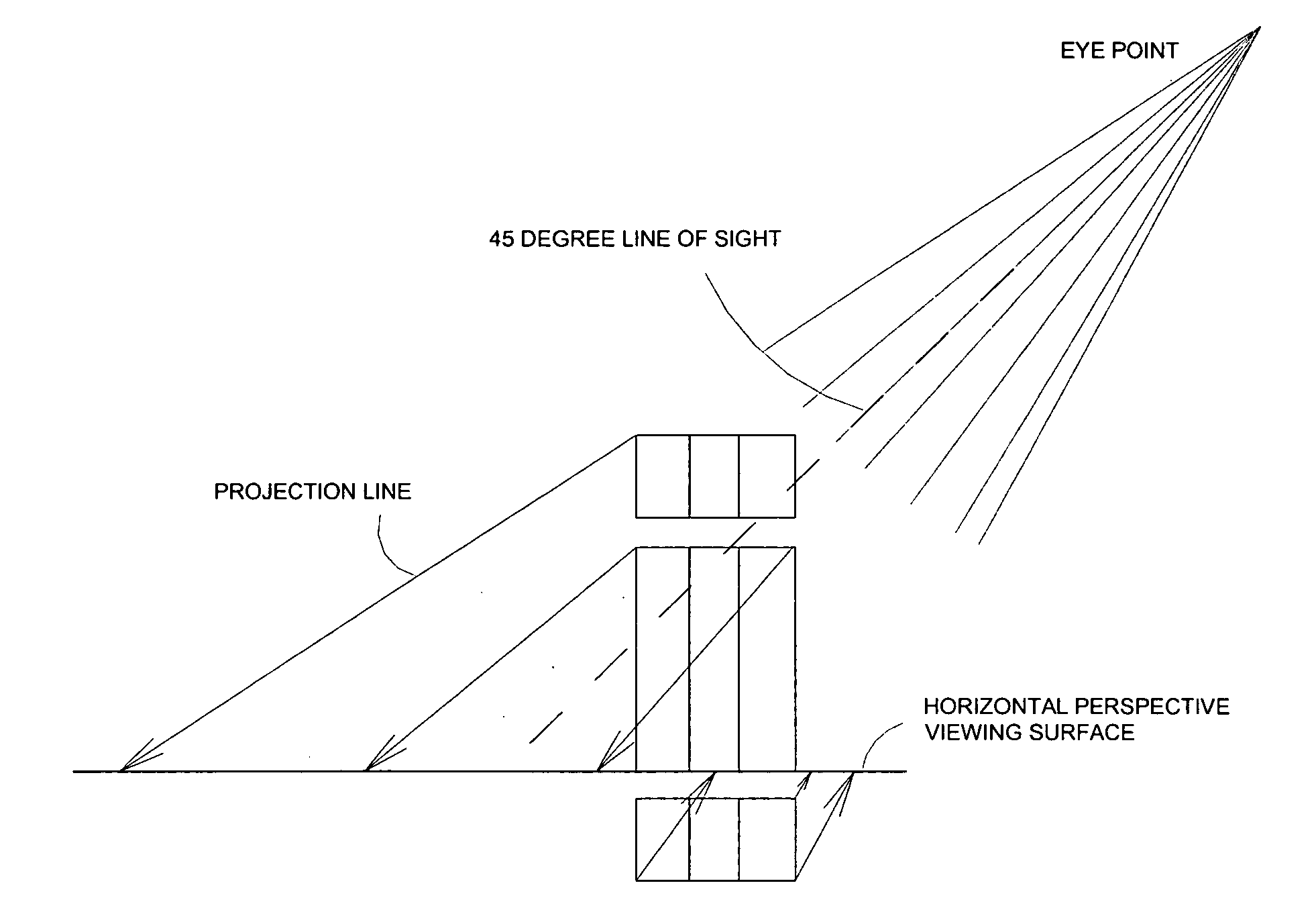
[0021] The present invention discloses a stereoscopic display system employing polarizing eyewear. The fundamental principle of stereoscopic display is that the two eyes sees slightly different images, and these two images are fused together to form the 3D illusion.

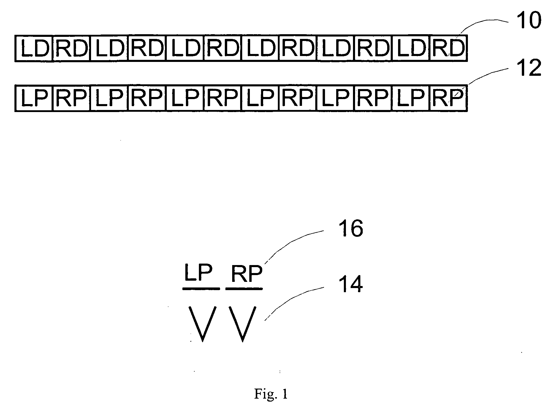
[0022] Polarizing eyewear employs polarizing filters to achieve the effect. The eyewear comprises mutually extinguished polarizing filters, such as orthogonal linear polarizer, circular polarizer, elliptical polarizer, for the two eyes. Correspondingly, the images are displayed through similar polarizer filters so that the eyes see proper images.

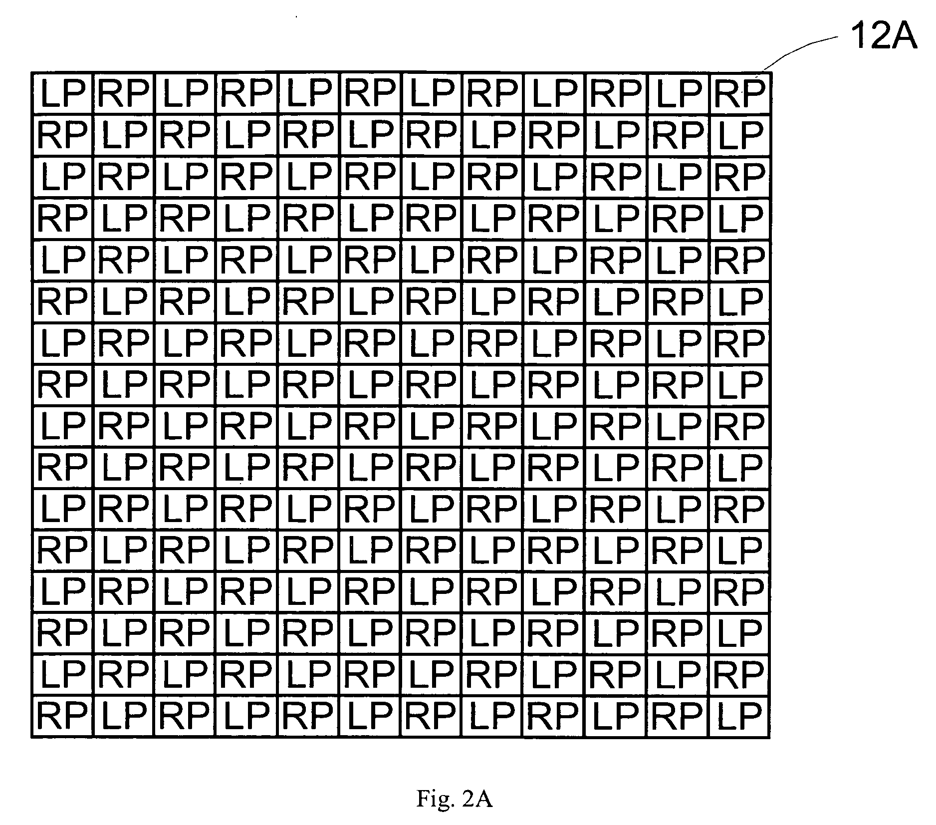
[0023] There are various ways to display polarized images such as spatially multiplexed, spatially supposition, or time sequentially. In spatially multiplexed method, the display comprises both the left and the right images, displayed through a dispersion pattern such as a checkerboard or alternate line. For example, in the alternate line pattern, all the odd lines display the l...


PUM


Abstract

The present invention discloses a stereoscopic display employing polarized eyewear. The basic component of the present invention stereoscopic display is a stereopolarizer, which is a polarized screen comprising microscopic sections of mutually extinguishing polarizing filters dispersed throughout the screen. To achieve the proper resolution, the size of the microscopic polarizing filter needs to be in order of micrometer, from a few microns to a few hundred of microns. The arrangement of the microscopic polarizing filters can be alternating stripes in horizontal, vertical, or any arbitrarily direction. The microscopic polarizing filters can be arranged in alternating pattern, such as alternating square or circle. The polarizer screen can be one sheet or can be a composite sheet, comprising two distinct polarizer filter sheet laminated together. Laser drilling is used to fabricate the microscopic polarizing filters, primarily due to ease of operation and appropriate microscopic sizes. Further, laser drilling and cutting can form angle holes in the stereopolarizer, which provides optimum focus viewing for horizontal perspective display.

Description

[0001] This application claims priority from U.S. provisional applications Ser. No. 60 / 709,269, filed Aug. 18, 2005, entitled “Stereoscopic display using polarized eyewear”, which is incorporated herein by reference.FIELD OF INVENTION [0002] This invention relates to a three-dimensional simulator system, and in particular, to a stereoscopic three-dimensional display using polarized eyewear. BACKGROUND OF THE INVENTION [0003] Ever since humans began to communicate through pictures, they faced a dilemma of how to accurately represent the three-dimensional (3D) world they lived in. The human eyes are two dimensional (2D) devices, and thus the brain is responsible for the three dimensional rendering. The disparity of the retinal images due to the separation of the two eyes is used to create the perception of depth. The effect is called stereoscopy where each eye receives a slightly different view of a scene, and the brain fuses them together using these differences to determine the rati...

Claims


Application Information

Patent Timeline
IPC IPC(8): H04N15/00
CPCH04N13/337G02B27/26G02B30/25
Inventor VESELY, MICHAEL A.CLEMENS, NANCY L.
Owner INFINITE Z
Why Eureka
Try Eureka