Combined effusion and thick TBC cooling method

a cooling method and effusion technology, applied in the direction of superimposed coating process, machine/engine, light and heating apparatus, etc., can solve the problems of reducing tbc deposits in cooling holes can detrimentally affect the service life of components, and the edge of the edge of the edge of the cooling hole can be chipped and cracked

Inactive Publication Date: 2006-01-26
HONEYWELL INT INC
View PDF21 Cites 35 Cited by
  • Summary
  • Abstract
  • Description
  • Claims
  • Application Information

AI Technical Summary

Problems solved by technology
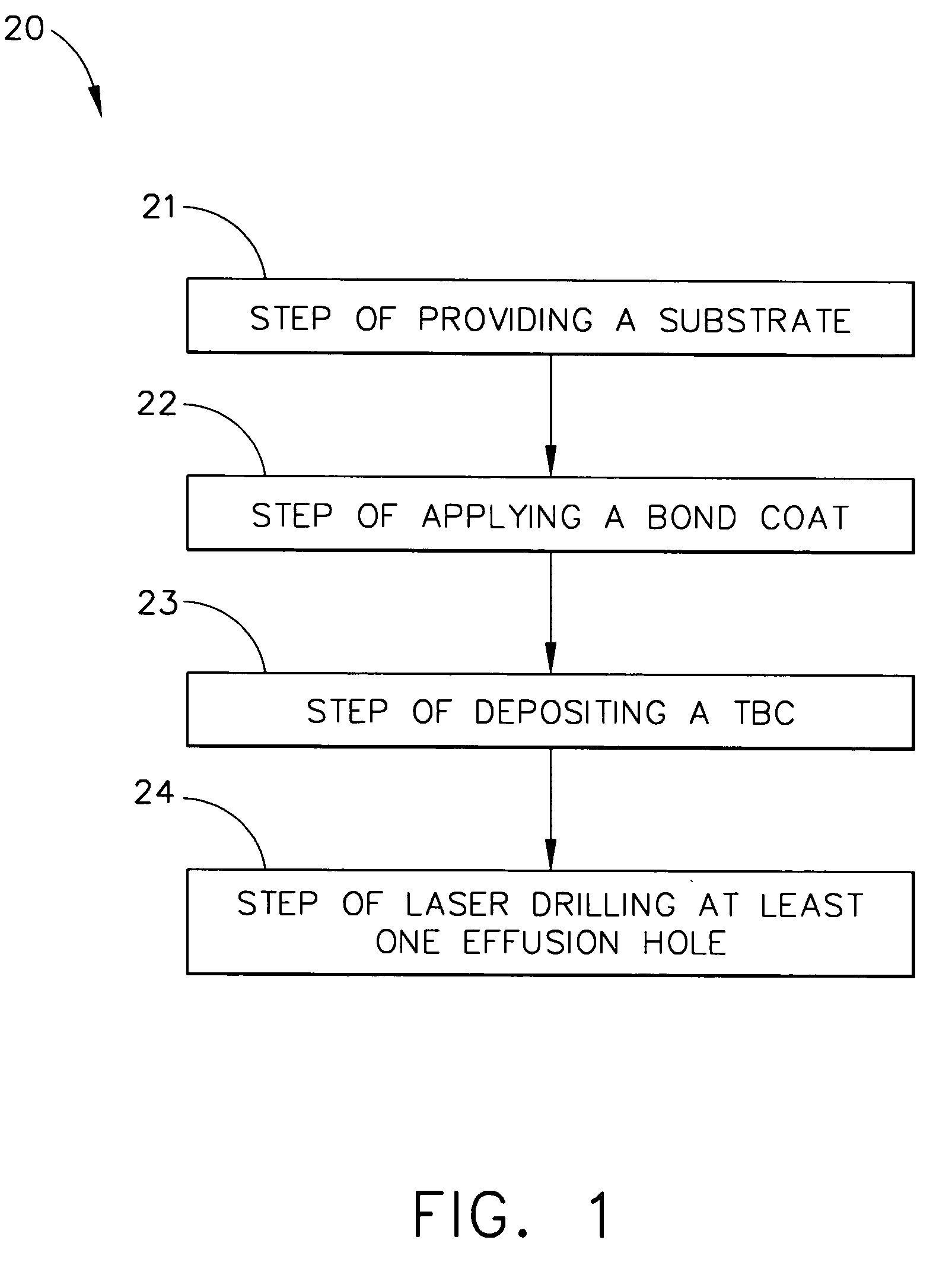
Gas turbine engine components, such as combustors, turbine blades, vanes, nozzles and shrouds, are exposed to temperatures that can reduce the operating life of the components.
The TBC deposits in the cooling holes can detrimentally affect the service life of the component because the TBC can alter the shape and reduce the size of the cooling holes.
When the masking material is removed, chipping and cracking often occurs along the edge due to the high cohesive strength of the TBCs in a direction horizontal to the plane of the substrate.
Additionally, chipping and cracking along the edge can serve as crack propagation sites for further degradation throughout the coating.
The erosion and abrasion caused by the abrasive particles in the water jet at pressures adequate to remove the TBC deposit also damages the cooling hole.
Additionally, for some applications, the abrasive media cannot be reused and must be disposed of, which increases production costs.
Unfortunately, following TBC deposition, this method also requires the holes to be cleaned by a water jet process.
Although the TBC deposited in the cooling holes in this example did not reduce fluid flow through the holes, this method may not be suitable for some applications.
Unfortunately, thicker TBCs are desired for some applications.
Although other methods have included cooling hole formation after TBC deposition, these methods are unsuitable when a thick TBC is desired.
Laser drilling is prone to spalling the brittle ceramic TBC by cracking the interface between the component substrate and the ceramic.
The spalling off severely reduces the sealing effectiveness and the insulative characteristics of the ceramic coating, causing component failure and expensive repairs.
EDM cannot be used to form cooling holes in a component having a TBC because the ceramic is electrically nonconducting.
Although cooling hole formation after TBC application may avoid excess TBC deposits, the described methods are unsuitable for some applications, especially for applications requiring thick TBC.
Further, methods are needed wherein cooling hole masking and / or cleaning processes are unnecessary.

Method used


Image

  • Combined effusion and thick TBC cooling method
  • Combined effusion and thick TBC cooling method
  • Combined effusion and thick TBC cooling method

Examples


example 1

[0048] A substrate comprising HA230™ (available from Haynes International) was formed into a 8″×12″ diameter cylinder. A bond coat comprising NiCrAlY, which had a nominal composition of 31 weight % Cr, 11 wt % Al, 0.5 wt % Y, and the balance Ni, was applied by plasma spray to a thickness of 0.0055 plus or minus 0.0025 inches. A TBC comprising 20 weight % yttria stabilized zirconia was deposited by Praxair Surface Technology, Inc. (Indianapolis, Ind.) to a thickness of 0.040 plus or minus 0.003 inches. The coated cylinder was laser drilled using conventional percussion on-the-fly laser drilling techniques. The TBC crack length vs laser pulse power setting (Joules) is shown in FIG. 6. For each power J setting, four holes were drilled. The holes each had a nominal diameter of 0.020 inch. The laser defocus, which is the distance of the lens focal point above the ceramic surface, was 0.08 inch. As can be seen, power setting 15.0 Joules resulted in TBC cracks ranging from about 0.00 to ab...

example 2

[0050] A substrate comprising HA230™ (available from Haynes International) was formed into a 8″×12″ diameter cylinder. A bond coat comprising NiCrAlY was applied by plasma spray to a thickness of 0.0055 plus or minus 0.0025 inches. A TBC comprising 20 weight % yttria stabilized zirconia was deposited by Praxair Surface Technology, Inc. to a thickness of 0.040 plus or minus 0.003 inches. The coated cylinder was laser drilled using conventional stationary percussion laser drilling techniques. The TBC interface crack length vs laser defocus relationship is shown in FIG. 8. Four holes were drilled for each laser defocus settings of 0.080, 0.125 and 0.250 inch. Three holes were drilled for the defocus setting of 0.500 inch. The holes each had a nominal diameter of 0.020 inch. As can be seen, laser defocus setting of 0.250 inch produced TBC interface cracks 36 ranging from about 0.005 to about 0.045 inches.

[0051]FIGS. 9a and 9b show cross-sectional views of the stationary percussion dril...

example 3

[0052] A substrate comprising HA230™ (available from Haynes International) was formed into a 8″×12″ diameter cylinder. A bond coat comprising NiCrAlY was applied by plasma spray to a thickness of 0.0055 plus or minus 0.0025 inches. A TBC comprising 20 weight % yttria stabilized zirconia was deposited by Praxair Surface Technology, Inc. to a thickness of 0.040 plus or minus 0.003 inches. The coated strip was laser drilled using conventional stationary percussion laser drilling techniques. The holes were drilled at laser pulse process settings of 9.4 J, 0.5 microsecond, 0.25″ defocus. A variety of pulses were used to drill four partial holes, shown in FIG. 10. These holes illustrate the propagation of percussion holes through the coating and initial penetration into the substrate. (These holes were not intended to penetrate the full thickness of the specimen.) The first hole 51 was formed using a series of 20 pulses, the second hole 52 was formed using 25 pulses, the third hole 53 was...


PUM

PropertyMeasurementUnit
thicknessaaaaaaaaaa
thicknessaaaaaaaaaa
thicknessaaaaaaaaaa

Abstract

A method for combined effusion and thick TBC cooling comprises a providing a substrate, depositing a thick TBC onto the substrate and laser drilling an array of effusion holes through the TBC coated substrate. The thick TBC has a columnar crack structure, which gives compliance and spall resistance. The microstructure of the segmentation microcracked TBC reduces cracking and chipping of the TBC during effusion hole laser drilling.

Description

GOVERNMENT INTERESTS [0001] The invention was made with Government support under contract with the US Army (DAAE07-02-3-0002). The Government has certain rights in this invention.BACKGROUND OF THE INVENTION [0002] The present invention generally relates to methods and apparatus for cooling components exposed to high temperatures, such as components of a gas turbine engine. More particularly, this invention relates to cooling methods and apparatus combining effusion cooling and thick thermal barrier coating (TBC). [0003] Gas turbine engine components, such as combustors, turbine blades, vanes, nozzles and shrouds, are exposed to temperatures that can reduce the operating life of the components. Effusion cooling and TBCs have been used extensively to improve component life. [0004] Effusion cooling comprises an array of effusion cooling holes through the component wall. A supply of cooling air is passed through the holes from the cooler surface of the component to the surface exposed t...

Claims


Application Information

Patent Timeline
Patent Type & Authority Applications(United States)
IPC IPC(8): F23R3/42
CPCC23C4/18F23M5/00F23M2900/05004F23R3/06F23R2900/03041C23C28/3455Y02T50/675C23C28/321C23C28/3215C23C28/345Y02T50/67Y02T50/60
Inventor WOODCOCK, GREGORY O.SILCOX, CHARLES P.STRANGMAN, THOMAS E.FLAMAND, LUIS M.KAWAMURA, HIROSHI
Owner HONEYWELL INT INC
Why Eureka
Try Eureka