Drawer-type vegetable-serving water tank of automatic cooking equipment
An automatic cooking and drawer-type technology, applied in cooking utensils, household utensils, applications, etc., can solve the problems of unstable dish center, cumbersome manual handling work, unsuitable for cooking equipment with a large amount of food, and achieve structural Reasonable, stable and reliable drawer structure
- Summary
- Abstract
- Description
- Claims
- Application Information
AI Technical Summary
Problems solved by technology
Method used
Image
Examples
Embodiment 1
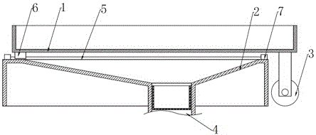
[0024] Such as figure 1 As shown, the drawer-type vegetable-discharging sink of the automatic cooking equipment in embodiment 1 includes a drawer 1 for holding the vegetable-discharging tray and a sink 2 located at the lower end of the drawer. The bottom surface of both sides of one end of the drawer 1 is provided with first casters 3, and the first casters 3. It is in contact with the base surface carrying the cooking equipment. The bottom surface of the drawer 1 and the top surface of the sink 2 are connected by sliding fit or rolling fit. The bottom end of the sink 1 is provided with a water outlet 4 communicating with the sewer pipe.
[0025] The sink 2 and the drawer 1 can be connected by sliding, but in order for the other end of the drawer to fall from above the sink, the top surface of the sink 2 is provided with a guide rail 5, the bottom surface of the drawer 1 is provided with a slider 6, and one end of the guide rail 5 is provided with a limit block 7 , the limit b...
Embodiment 2
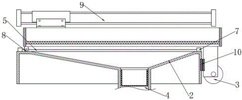
[0029] Such as figure 2 As shown, the difference between embodiment 2 and embodiment 1 is that fixed pulleys 8 are respectively provided on both sides of the bottom surface of the other end of the drawer 1 , and guide rails 5 matched with the fixed pulleys 8 are provided on the top surface of the water tank 2 .
[0030] In Embodiment 2, the drawer 1 includes a drawer frame 101 and a drawer bottom 102, the drawer bottom 102 is fixedly connected to the drawer frame 101, and a through hole is provided on the drawer bottom.
[0031] The drawer is cooperatively connected with the reciprocating drive mechanism, and the reciprocating drive mechanism is used to drive the drawer to reciprocate axially along the guide rail. The above scheme can realize the automatic translation of the drawer. The reciprocating drive mechanism is the first cylinder 9, and the cylinder is a rodless cylinder, and the piston rod of the first cylinder is fixedly connected with the drawer frame.
[0032] T...
Embodiment 3
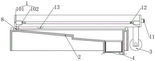
[0035] Such as image 3 and 4 As shown, the difference between Embodiment 3 and Embodiment 2 is that a handle 11 is provided on one end surface of the drawer 1 . It should be noted that the guide rail 5 in the third embodiment extends to the side of the water tank 2 .
[0036] The drawer bottom 102 is provided with a positioning ring 12 , and the positioning ring 12 is fixedly connected with the drawer frame 101 .
[0037] The tank bottom of the water tank 2 is a stepped inclined surface.
[0038] There is also a hidden second caster 13 between the first caster 3 and the bottom surface of the other end of the drawer, that is, the second caster is arranged between the first caster 3 and the fixed pulley 8, and the second caster 13 is connected to the drawer frame through the bracket 14. 101 connection, the bottom surface of the drawer frame 101 is provided with a cavity for accommodating the second caster 13 and the bracket 14 . Specifically, the bracket 14 includes a conne...
PUM
 Abstract
Description
Claims
Application Information
 - R&D
- Intellectual Property
- Life Sciences
- Materials
- Tech Scout
- Unparalleled Data Quality
- Higher Quality Content
- 60% Fewer Hallucinations
Browse by: Latest US Patents, China's latest patents, Technical Efficacy Thesaurus, Application Domain, Technology Topic, Popular Technical Reports.
© 2025 PatSnap. All rights reserved.Legal|Privacy policy|Modern Slavery Act Transparency Statement|Sitemap|About US| Contact US: help@patsnap.com


