
Remote control steam hammer for engineering

A technology of steam hammer and steam, applied in the direction of power hammer and hammer driving device, etc., can solve the problems of unreasonable utilization of resources, inconvenient use of workers, vibration and noise, etc., and achieve the effects of saving manpower and material resources, increasing speed and convenient operation

Inactive Publication Date: 2017-05-31
王鸣铎
View PDF0 Cites 2 Cited by
  • Summary
  • Abstract
  • Description
  • Claims
  • Application Information

AI Technical Summary

Problems solved by technology

[0002] Steam hammer refers to a mechanical hammer driven by water vapor. The hammer head and the piston rod device of the cylinder can move up and down to hammer forgings. The forging hammer uses a large anvil or a movable lower hammer head as the supporting surface for striking. During the working stroke, the striking speed of the hammer head drops to zero instantly. The work is impactful and can produce a large striking force, which usually causes great vibration and noise. The existing forging hammers are divided according to the striking characteristics. Hammer and hammer with anvil; according to the process, there are free forging hammer, die forging hammer and sheet stamping hammer; but most of the existing forging hammers are electric, and many factories will produce high-pressure steam, which cannot be used reasonably resources, and the existing forging hammers are all control handles, which brings inconvenience to workers

Method used


Image

  • Remote control steam hammer for engineering

Examples


Embodiment Construction

[0012] The following will clearly and completely describe the technical solutions in the embodiments of the present invention with reference to the accompanying drawings in the embodiments of the present invention. Obviously, the described embodiments are only some, not all, embodiments of the present invention. Based on the embodiments of the present invention, all other embodiments obtained by persons of ordinary skill in the art without making creative efforts belong to the protection scope of the present invention.

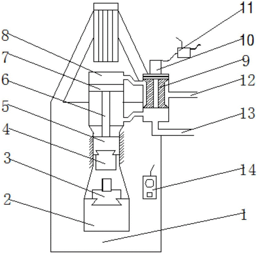
[0013] see figure 1 , the present invention provides a technical solution: a remote control steam hammer for engineering, comprising a pier 1, a lower anvil 2, a workpiece fixture 3, a hammer head 4, an upper anvil 5, a piston rod 6, a piston 7, a steam cylinder 8, a steam Slide valve 9, electromagnetic starting tube 10, signal receiving controller 11, steam inlet pipe 12, steam exhaust pipe 13 and remote controller 14, lower anvil 2 is arranged on the upper s...


PUM

PropertyMeasurementUnit
Diameteraaaaaaaaaa

Abstract

The invention discloses a remote control steam hammer for engineering. The remote control steam hammer comprises a pier base, a lower anvil, a workpiece holder, a hammerhead, an upper anvil, a piston rod, a piston, a steam cylinder, a steam sliding valve, an electromagnetic starting cylinder, a signal receiving controller, a steam inlet pipe, a steam exhaust pipe and a remote control, wherein the lower anvil is arranged on the upper side of the pier base, the workpiece holder is arranged on the upper side of the lower anvil, the hammerhead is arranged on the upper side of the workpiece holder, the upper anvil is arranged on the upper side of the hammerhead, the piston rod is arranged on the upper side of the upper anvil, the piston is arranged on the upper side of the piston rod, the steam cylinder is arranged on the upper side of the piston, the steam sliding valve is arranged on the right side of the steam cylinder, the electromagnetic starting cylinder is arranged on the upper side of the steam sliding valve, and the signal receiving controller is arranged on the right side of the electromagnetic starting cylinder. The remote control steam hammer for engineering is provided with the steam sliding valve and the electromagnetic starting cylinder and has the advantages of high degree of automation and convenience in operation, a large quantity of manpower and material resources are saved, and the forging speed is effectively increased.

Description

technical field [0001] The invention relates to the technical field of steam hammer forging, in particular to a remote-controlled steam hammer for engineering. Background technique [0002] Steam hammer refers to a mechanical hammer driven by water vapor. The hammer head and the piston rod device of the cylinder can move up and down to hammer forgings. The forging hammer uses a large anvil or a movable lower hammer head as the supporting surface for striking. During the working stroke, the striking speed of the hammer head drops to zero instantly. The work is impactful and can produce a large striking force, which usually causes great vibration and noise. The existing forging hammers are divided according to the striking characteristics. Hammer and hammer with anvil; according to the process, there are free forging hammer, die forging hammer and sheet stamping hammer; but most of the existing forging hammers are electric, and many factories will produce high-pressure steam, ...

Claims


Application Information

Patent Timeline
IPC IPC(8): B21J7/04B21J7/24
CPCB21J7/04B21J7/24
Inventor 王鸣铎
Owner 王鸣铎
Learn More