
Vibration casting sand cleaning machine

A vibration-type, sand cleaning machine technology, applied in the field of foundry equipment, can solve the problems of easy fatigue, low sand cleaning efficiency, high labor intensity, etc., and achieve the effect of high sand cleaning efficiency

Active Publication Date: 2018-07-10
YONGCHUAN DISTRICT CHONGQING HUAYI MACHINERY CASTING CO LTD
View PDF7 Cites 0 Cited by
  • Summary
  • Abstract
  • Description
  • Claims
  • Application Information

AI Technical Summary

Problems solved by technology

However, sand cleaning is a job with high labor intensity and harsh working environment in the casting industry, which will have a great impact on the health and safety of workers during the process of sand cleaning
Moreover, the cleaning speed of castings in this way is slow, the processing efficiency is very low, and the cost of cleaning is relatively high
[0003] At present, there are also some sand cleaning machines for sand cleaning. However, in the process of sand cleaning, the existing sand cleaning machines still need to manually put the castings in place, and turn the castings manually.
Although this method reduces the labor load of manual cleaning, it still requires manual operation during the process of placing and turning the casting, and manual operation is prone to fatigue, which ultimately leads to low sand cleaning efficiency.

Method used


Image

  • Vibration casting sand cleaning machine
  • Vibration casting sand cleaning machine
  • Vibration casting sand cleaning machine

Examples


Embodiment Construction

[0016] The present invention will be described in further detail below by means of specific embodiments:

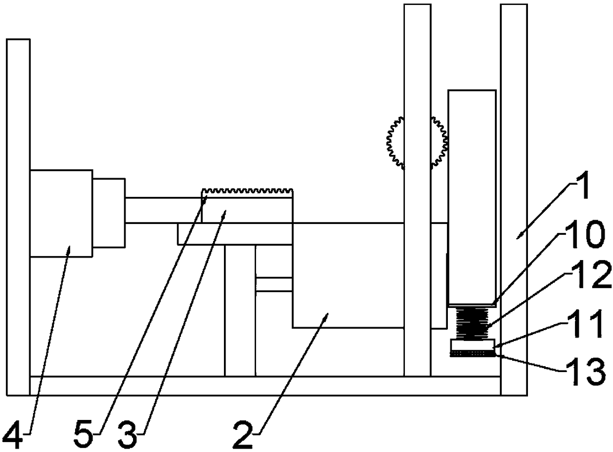
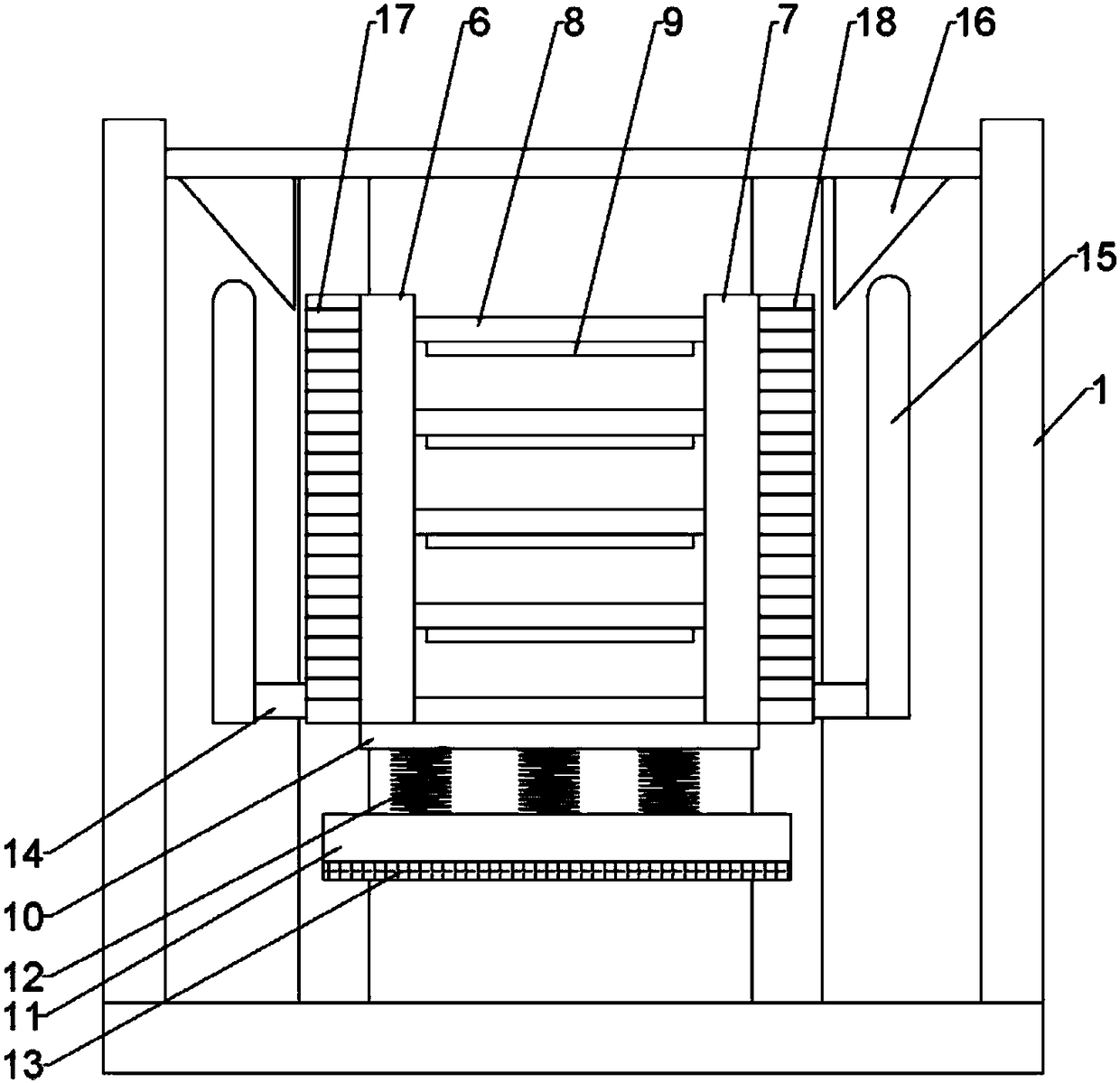
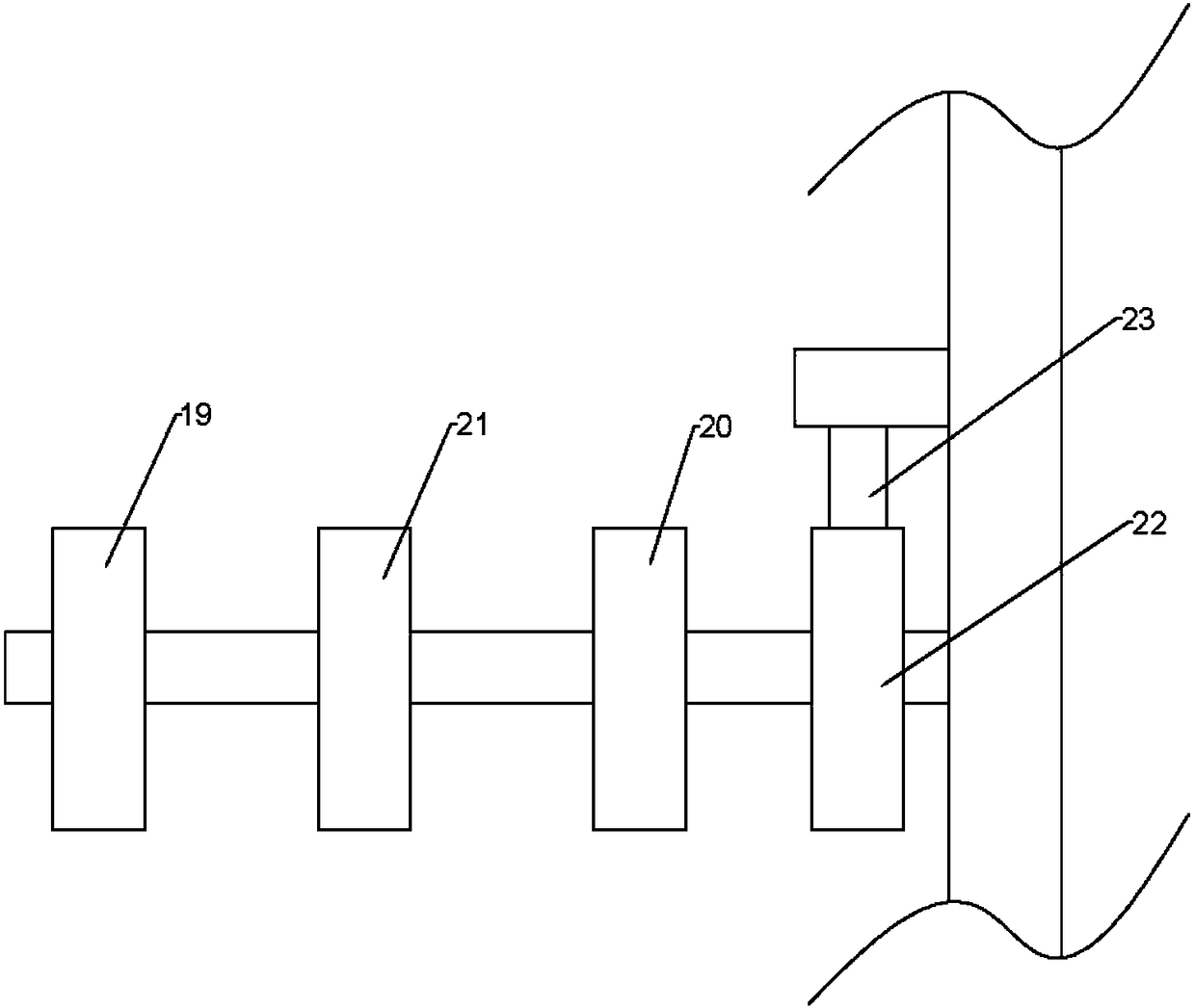
[0017] The reference signs in the drawings of the description include: frame 1, conveyor belt 2, push plate 3, cylinder 4, first rack 5, first vertical plate 6, second vertical plate 7, groove 8, sand storage box 9. First bottom plate 10, second bottom plate 11, spring 12, rubber layer 13, pin 14, connecting rod 15, wedge 16, second rack 17, third rack 18, first gear 19, second gear 20, the third gear 21, the ratchet 22, and the ratchet 23.

[0018] Example basic reference figure 1 , figure 2 and image 3 Shown: Vibration casting sand cleaning machine, including frame 1, frame 1 is provided with conveyor belt 2, and the left side of conveyor belt 2 is provided with push plate 3, push plate 3 is slidably connected to frame 1, push plate 3 The left side is threadedly connected with a cylinder 4, the cylinder 4 is fixedly connected to the frame 1 by bolts, the upper end...


PUM


Abstract

The invention provides a vibration type casting sand cleaning machine and relates to the field of casting equipment. The vibration type casting sand cleaning machine comprises a rack and a casting platform, wherein a push plate is arranged at one side of the casting platform; the upper end face of the push plate is connected with a first rack; a storage rack is arranged at the other side of the casting platform; the storage rack comprises a first vertical plate and a second vertical plate; a groove is connected between the first vertical plate and the second vertical plate; the first vertical plate is in sliding connection with a first bracket; the second vertical plate is in sliding connection with a second bracket; pins are arranged between the first vertical plate and the first bracket, and between the second vertical plate and the second bracket; the pins are fixedly connected with a connecting rod parallel to the first bracket, and a wedge block is arranged above the connecting rod; a second rack is connected with one side, close to the casting platform, of the first bracket; a third rack is connected with one side, close to the casting platform, of the second bracket; the second rack is engaged with a first gear; the third rack is engaged with a second gear; the first gear and the second gear are coaxially connected with a third gear and a ratchet wheel; and the ratchet wheel is engaged with a pawl. Compared with the prior art, the vibration type casting sand cleaning machine has relatively high casting sand cleaning efficiency.

Description

technical field [0001] The invention relates to the field of casting equipment, in particular to a vibrating sand cleaning machine for castings. Background technique [0002] Sand cleaning of castings is a very important process in the casting process. At present, the work of sand cleaning is generally carried out by manual sand cleaning. However, sand cleaning is a job with high labor intensity and harsh working environment in the casting industry, which will have a great impact on the health and safety of workers in the process of sand cleaning. Moreover, the cleaning speed of castings in this way is relatively slow, the processing efficiency is very low, and the cost of cleaning is relatively high. [0003] At present, there are also some sand cleaning machines for sand cleaning. However, in the process of sand cleaning, the existing sand cleaning machines still need to manually place the castings and turn the castings manually. Although this method reduces the labor l...

Claims


Application Information

Patent Timeline
Patent Type & Authority Patents(China)
IPC IPC(8): B22D31/00
CPCB22D31/002
Inventor 孔锐
Owner YONGCHUAN DISTRICT CHONGQING HUAYI MACHINERY CASTING CO LTD
Learn More