Process for manufacturing shell of impeller of electrical pump

A manufacturing process and impeller technology, which is applied to the components, pumps, and pump components of pumping devices for elastic fluids, can solve the problems of long production cycle, high rejection rate, narrow flow channels, etc., and achieves improved labor efficiency, The effect of short production cycle and improved yield

Active Publication Date: 2013-09-18
山东燕山精密机械有限公司
View PDF4 Cites 0 Cited by
  • Summary
  • Abstract
  • Description
  • Claims
  • Application Information

AI Technical Summary

Problems solved by technology

[0002] The impeller is one of the main components of the electric pump and plays a very important role in the electric pump. Because the flow channel of the impeller is a curved surface with a complex structure, and the flow channel is narrow and deep, it increases the difficulty of manufacturing the impeller shell.
Manufactured according to the general process, there are disadvantages of high scrap rate, long production cycle, and castings are not easy to remove sand, so the design of the casting process of the impeller is particularly important. If the casting process is not correct, it will cause internal leakage of molten steel in the flow channel of the impeller shell during pouring. scrap casting
Blind production will cause great economic losses, so the manufacturing method of the shell is a very important link, which directly affects the pass rate of castings

Method used


Image

  • Process for manufacturing shell of impeller of electrical pump
  • Process for manufacturing shell of impeller of electrical pump

Examples


Embodiment 1

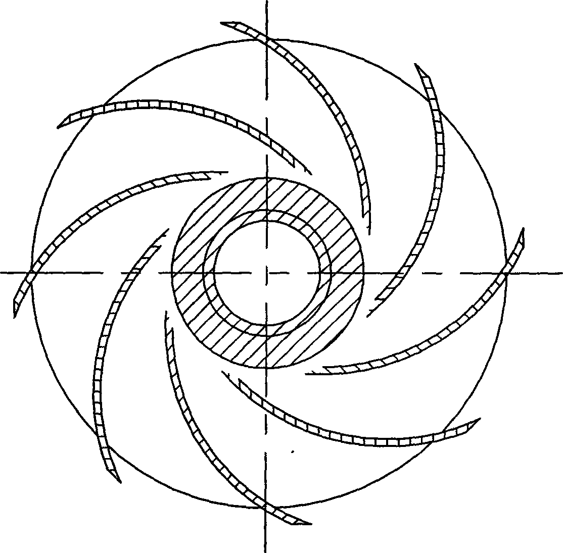
[0027] Example 1: Prepare a casing of an electric pump impeller with a channel height of 7.5mm, the steps are as follows:

[0028] 1) Shell making: use zircon powder slurry and mullite powder slurry to sizing, sanding and drying the impeller wax model layer by layer;

[0029] The zircon powder slurry is obtained in the following way: 100kg S830 silica sol, 450g wetting agent, 220g defoamer, 380kg 300 mesh zircon powder are added in the empty slurry tank successively; when adding 300 mesh zircon powder , While adding, use manual auxiliary stirring to prevent the 300-mesh zircon powder from accumulating and agglomerating during the addition process. After the 300-mesh zircon powder is added, measure the flow rate after 2 hours and add 1.2Kg of zircon powder for 32 seconds. , After fully stirring for 26 hours by the rotation of the slurry bucket, measure its flow rate again to be 35 seconds.

[0030] The mullite slurry is obtained by adding 90kg S1420 silica sol and 140KG200 pur...

Embodiment 2

[0037] Embodiment 2: an electric pump impeller with a channel height of 6 mm, the steps are the same as in Embodiment 1, wherein the processes involved in step 1) are shown in Table 2:

[0038] Table 2

[0039] level

[0040]

[0041] The test proves that all 75 impellers poured into the shells manufactured in Examples 1 and 2 are qualified, and the shells in the runners are very easy to remove during the sand cleaning process of the shells.


PUM


Abstract

The invention discloses a process for manufacturing a shell of an impeller of an electrical pump, which comprises: 1) a step of shell manufacturing, in which a wax mold of the impeller is subjected to sizing, stuccoing and drying layer by layer by zircon powder slurry and mullite sand slurry; 2) a step of dewaxing under conditions of a pressure of between 0.6 and 0.75 MP and a temperature of between 150 and 170 DEC C for 6 to 10 minutes; and 3) a step of roasting, in which the roasting temperature is 1,000 to 1,100 DEG C, and the temperature is kept for at least 30 minutes when the resulting product of the dewaxing reaches the temperature. The shell of the impeller of the electrical pump manufactured by the invention has the advantages that: the rate of leaking shell is low; and at the same time, a flow passage is filled with dry and scattered mullite sand, so the shell in the flow passage is easy to clean after a casting is poured, labor efficiency is greatly improved, and consequently the rate finished casting and the sand cleaning efficiency are improved. The preparation process of the invention has the advantages of high rate of finished product, short production period, easy sand cleaning and the like.

Description

technical field [0001] The invention relates to a manufacturing process of an electric pump impeller shell, in particular to a manufacturing process of a precision casting shell with a flow channel height less than 10 mm, a complex inner cavity, and a space curved surface type electric pump impeller, which belongs to the electric pump impeller manufacturing technology. Background technique [0002] The impeller is one of the main components of the electric pump and plays a very important role in the electric pump. Because the flow channel of the impeller is a curved surface with a complex structure, and the flow channel is narrow and deep, it increases the difficulty of manufacturing the impeller shell. . Manufactured according to the general process, there are disadvantages of high scrap rate, long production cycle, and castings are not easy to remove sand, so the design of the casting process of the impeller is particularly important. If the casting process is not correct...

Claims


Application Information

Patent Timeline
Patent Type & Authority Patents(China)
IPC IPC(8): F04D29/22
Inventor 陈培敦赵星曹旭东赵士锋刘祥银王爱霞房亮刘呈俊
Owner 山东燕山精密机械有限公司
Why Eureka
Try Eureka