
Loading device for casting moulds

A loading device and casting mold technology, which is applied to casting equipment, manufacturing tools, and mold handling equipment, can solve the problems of large labor consumption, reduced service life of casting molds, and large losses, so as to ensure product quality and castings quality and life-enhancing effects

Active Publication Date: 2017-05-31
重庆市璧山正发有色金属有限公司
View PDF4 Cites 4 Cited by
  • Summary
  • Abstract
  • Description
  • Claims
  • Application Information

AI Technical Summary

Problems solved by technology

[0003] 1. In the process of transshipment, affected by factors such as the size of the workshop and the limitation of process requirements, the casting mold will shake, tilt, etc. during the flow of the production line, which directly affects the quality of the sand mold, thereby affecting the quality of the product and reducing the casting cost. The service life of the mold has a large loss
[0004] 2. The transfer and installation process of casting molds consume a lot of labor and time, and the production efficiency is extremely low;
[0005] 3. During the installation process of the casting mold, it is also easy to appear that the casting mold is not placed flat and produce bad castings, which leads to the scrapping of materials, brings losses to the enterprise, and increases production costs

Method used


Image

  • Loading device for casting moulds
  • Loading device for casting moulds
  • Loading device for casting moulds

Examples


Embodiment Construction

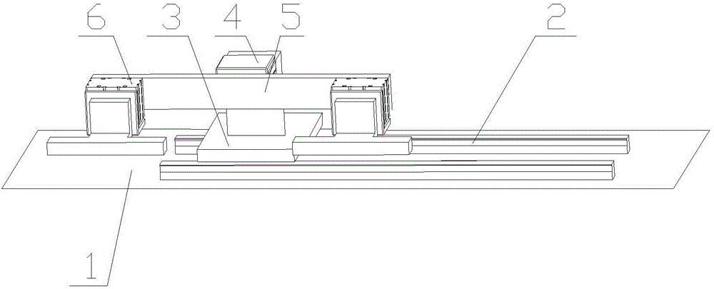
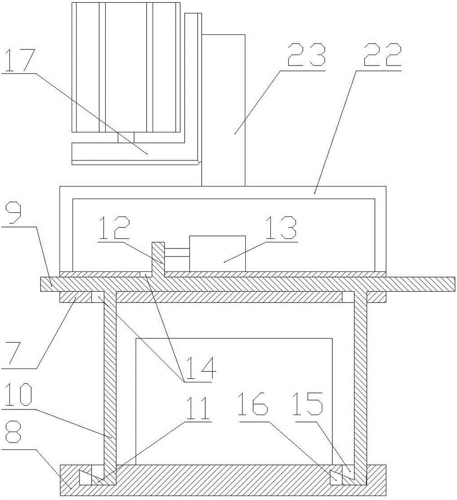
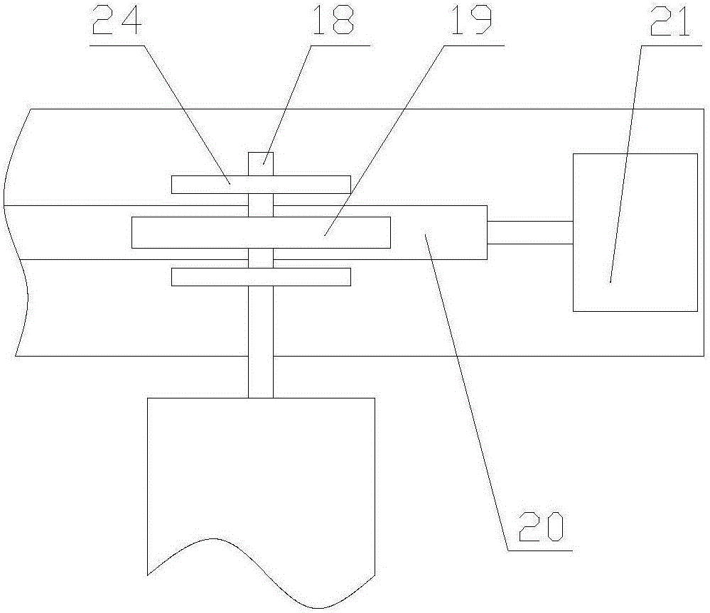
[0022] see Figure 2 to Figure 3 , a loading device for a casting mold, comprising an upper plate, a lower plate and a lifting device, a slide plate is slidably fitted in the upper plate, and a chute for the slide plate to slide longitudinally along the upper plate is provided in the upper plate, and the slide plate There are two downwardly extending hook plates located at the two longitudinal ends of the slide plate. The hook plates include a vertical plate and a hook head located at the lower end of the vertical section. The upper end of the slide plate is provided with an upwardly extending connecting plate, and a push-pull cylinder is fixed on the upper end of the upper plate, and the piston rod of the push-pull cylinder is fixedly connected with the connecting plate for pushing the slide plate to slide longitudinally along the upper plate. The slide plate is provided with a relief opening for the vertical plate and the connecting plate to slide longitudinally along the up...


PUM


Abstract

The invention discloses a loading device for casting moulds. According to the loading device for the casting moulds, the labor intensity of workers is lowered, the casting quality is higher, and production efficiency is improved. The loading device comprises an upper plate, a lower plate and a lifting device. The upper plate is internally slidably matched with a sliding plate, two hook plates are arranged below the sliding plate, and each hook plate comprises a vertical plate and a hook head located at the lower end of the corresponding vertical plate. The vertical plates are arranged in the transverse direction of the sliding plate, a connecting plate upwards extending is arranged at the upper end of the sliding plate, and a push-pull air cylinder is fixed to the upper end of the upper plate. A piston of the push-pull air cylinder is fixedly connected with the connecting plate and is used for pushing the sliding plate to longitudinally slide along the upper plate. Position giving openings for the vertical plates and the connecting plate to longitudinally slide along the upper plate are formed in the sliding plate. The lower plate is used for loading the moulds, and inserting grooves are formed in the lower plate, correspond to the hook heads and are used for inserting of the hook heads. A hook groove is formed in one side of each inserting groove, and the hook heads can be pushed to be matched with the hook grooves under the effect of the push-pull air cylinder. The lifting device is connected with the upper plate and used for driving the upper plate to rise and fall.

Description

technical field [0001] The invention relates to the field of casting, in particular to a loading device for a casting mold. Background technique [0002] In the production line of equipment that uses molds for casting, the transfer of casting molds has always been placed on two rows of rollers, and the rotation of the rollers is used to complete the recycling of casting molds on the production line. However, this transport method has the following disadvantages: [0003] 1. In the process of transshipment, affected by factors such as the size of the workshop and the limitation of process requirements, the casting mold will shake, tilt, etc. during the flow of the production line, which directly affects the quality of the sand mold, thereby affecting the quality of the product and reducing the casting cost. The service life of the mold has a greater loss. [0004] 2. The transfer and installation process of casting molds consume a lot of labor and time, and the production e...

Claims


Application Information

Patent Timeline
Patent Type & Authority Applications(China)
IPC IPC(8): B22D33/06
CPCB22D33/06
Inventor 周伦
Owner 重庆市璧山正发有色金属有限公司
Learn More