
Method for filling solder

A filling method and solder technology, applied in welding equipment, tin feeding devices, metal processing equipment, etc., can solve problems such as affecting the filling effect, and achieve the effect of optimizing the filling effect and reducing dust and water vapor.

Inactive Publication Date: 2017-05-31
南通沃特光电科技有限公司
View PDF4 Cites 0 Cited by
  • Summary
  • Abstract
  • Description
  • Claims
  • Application Information

AI Technical Summary

Problems solved by technology

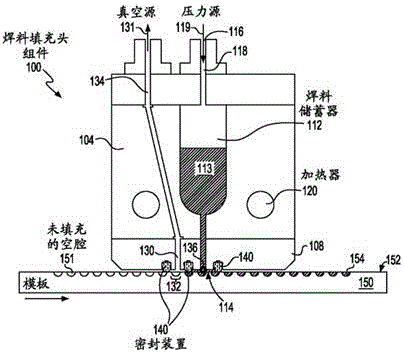
[0005] However, there are still problems in the above method. Although the trapped air is taken away by the vacuum device, dust or water vapor will be generated in the cavity during the corrosion or drilling process, which will affect the filling effect when filling the solder.

Method used


Image

  • Method for filling solder
  • Method for filling solder
  • Method for filling solder

Examples


Embodiment Construction

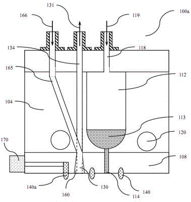
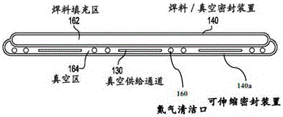
[0021] see figure 2 , the present invention provides a solder filling device 100a, characterized in that it comprises: at least one chamber 112 for holding molten solder 113, said chamber 112 having an outlet 114 for discharging said molten solder; positioned at sealing means 140 on opposite sides of the molten solder 113 outlet; having a vacuum means inlet 130 adjacent to the molten solder outlet 114; positioned on the side of the vacuum means inlet 130 on the side of the sealing means The retractable sealing device 140a constituting the vacuum area; there is also a gas cleaning outlet 160 in the vacuum area, and the gas source 165 communicates with the gas cleaning outlet 160 through a gas tube 166 . During operation, only one of the gas cleaning outlet 160 and the vacuum device inlet 130 can be opened. When the gas cleaning outlet 160 is opened, the cavity contacting the workpiece is cleaned, and the retractable sealing device 140a is in an unsealed state. When the inlet...


PUM


Abstract

The invention provides a method for filling a solder. The method comprises the following steps: (1) setting a stretchable sealing device to be in a non-sealing state, keeping an outlet of a vacuum device to be in a closed state, and supplying jet gas for cleaning gas to a to-be-filled chamber of a workpiece from a gas cleaning inlet; (2) setting the stretchable sealing device to be in a sealing state, keeping the gas cleaning inlet closed, and performing vacuum treatment on the chamber through the vacuum device; and (3) moving the workpiece or a solder filling device, locating the chamber after the vacuum treatment under a fused solder inlet, and then filling the solder.

Description

technical field [0001] The invention relates to the field of solder filling, in particular to a filling method using a solder filling device with vacuum and cleaning components. Background technique [0002] Existing precision and other pattern filling processes, e.g., filling features in semiconductors (e.g. integrated circuits, chip technology and chip packaging) or features on semiconductor chips (e.g. cavities / cavities or trenches created by etching ). The feature can be filled with a substance, which can be solder. [0003] In the existing feature filling process, due to the presence of air when filling the cavity / cavity or trench, the joint between the solder and the cavity / cavity or trench is defective, resulting in unreliable joint. To solve this problem, a vacuum cavity can be used to remove trapped gas before filling. For details, see figure 1 , a filling head apparatus 100 body 104 and a filling head 108 attached to the body 104 . Body 104 includes a sealed s...

Claims


Application Information

Patent Timeline
IPC IPC(8): B23K3/06
CPCB23K3/0607
Inventor 王汉清
Owner 南通沃特光电科技有限公司
Learn More