
Tin bar granulator

A technology of granulator and tin bar, applied in metal processing equipment, welding equipment, manufacturing tools, etc., can solve the problems of unconnected pins and incomplete welding, etc., and achieve the effect of preventing reverse movement

Active Publication Date: 2017-05-31
ALEADER VISION TECH
View PDF11 Cites 3 Cited by
  • Summary
  • Abstract
  • Description
  • Claims
  • Application Information

AI Technical Summary

Problems solved by technology

[0002] In the production line of surface mount technology, the printing machine is the first to play a role. However, the process of printing solder paste on the printing machine cannot guarantee that there will be enough tin material in every place that needs tin material. In the process of chipping, where there is less tin material, it is easy to cause incomplete soldering, or the pins are not connected directly.

Method used


Image

  • Tin bar granulator
  • Tin bar granulator
  • Tin bar granulator

Examples


Embodiment Construction

[0023] The technical solutions of the present invention will be further described below in conjunction with the accompanying drawings and through specific implementation methods.

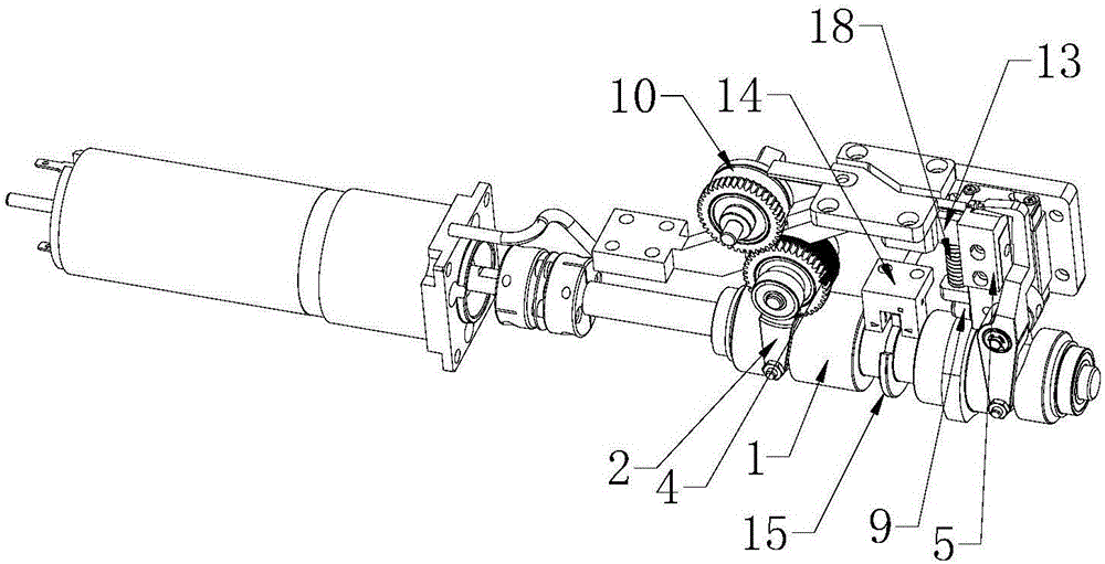
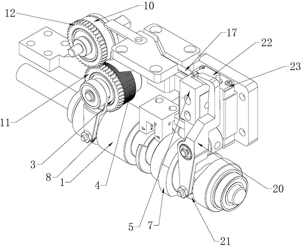
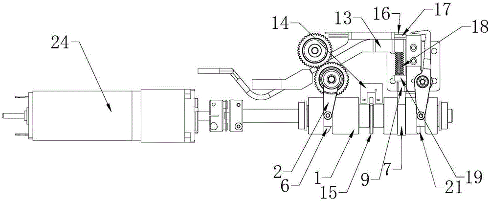
[0024] Such as Figure 1~4 As shown, in this embodiment, a tin bar granulator includes a rotating shaft 1, a swing rod 2, a one-way bearing 3, a conveying wheel 4, a cutting knife block 5, a first cylindrical cam groove 6 and a disc-shaped Cam 7, the first cylindrical cam groove 6 surrounds the outer surface of the rotating shaft 1, one end of the swing rod 2 is connected to the first cylindrical cam groove 6, and the swing rod 2 is far away from the first cylindrical cam groove One end of a cylindrical cam groove 6 is connected with the one-way bearing 3, the delivery wheel 4 is sleeved on the outer surface of the one-way bearing 3, the rotating shaft 1 passes through the disc cam 7 and is connected with the one-way bearing 3. The disk-shaped cam 7 is relatively fixed, and the cutting knife block ...


PUM


Abstract

The invention discloses a tin bar granulator which comprises a rotary shaft, an oscillating rod, a one-way bearing, a conveying wheel, a cutting knife block, a first cylindrical cam groove and a disc cam. The first cylindrical cam groove is formed in positions around the outer side surface of the rotary shaft, an end of the oscillating rod is connected with the first cylindrical cam groove, the end, which is far away from the first cylindrical cam groove, of the oscillating rod is connected with the one-way bearing, the conveying wheel sleeves the outer side surface of the one-way bearing, the rotary shaft penetrates the disc cam and is fixed relative to the disc cam, and the cutting knife block is connected with the disc cam in a butted manner. The tin bar granulator has the advantages that tin bars can be driven and conveyed by the rotary shaft and can be positioned and cut by the same rotary shaft when the tin bars are cut to obtain granules, and the one-way bearing can prevent the tin bars from reversely moving.

Description

technical field [0001] The invention relates to the technical field of surface mounting technology equipment, in particular to a tin bar pelletizer. Background technique [0002] In the production line of surface mount technology, the printing machine is the first to play a role. However, the process of printing solder paste on the printing machine cannot guarantee that there will be enough tin material in every place that needs tin material. In the process of chipping, where there is less tin material, it is easy to cause incomplete soldering, or the pins are not connected directly. Therefore, the operation of replenishing tin is very necessary. However, it is not possible to add a large-scale equipment or instrument directly in the small place of the placement machine to replenish tin in places with less tin. Therefore, a component is required A machine that is less and can provide small pieces of tin particles required for tin filling at the same time. Contents of the ...

Claims


Application Information

Patent Timeline
Patent Type & Authority Applications(China)
IPC IPC(8): B23K3/08
CPCB23K3/082
Inventor 卢奇
Owner ALEADER VISION TECH
Learn More