Sea wave energy conversion device and sea wave energy conversion method
A conversion device and conversion method technology, applied in ocean energy power generation, engine components, machines/engines, etc., can solve the problems of low efficiency, many intermediate links in wave energy conversion methods, etc., to reduce manufacturing costs, high energy conversion efficiency, The effect of reducing power output fluctuations
- Summary
- Abstract
- Description
- Claims
- Application Information
AI Technical Summary
Problems solved by technology
Method used
Image
Examples
Embodiment 1
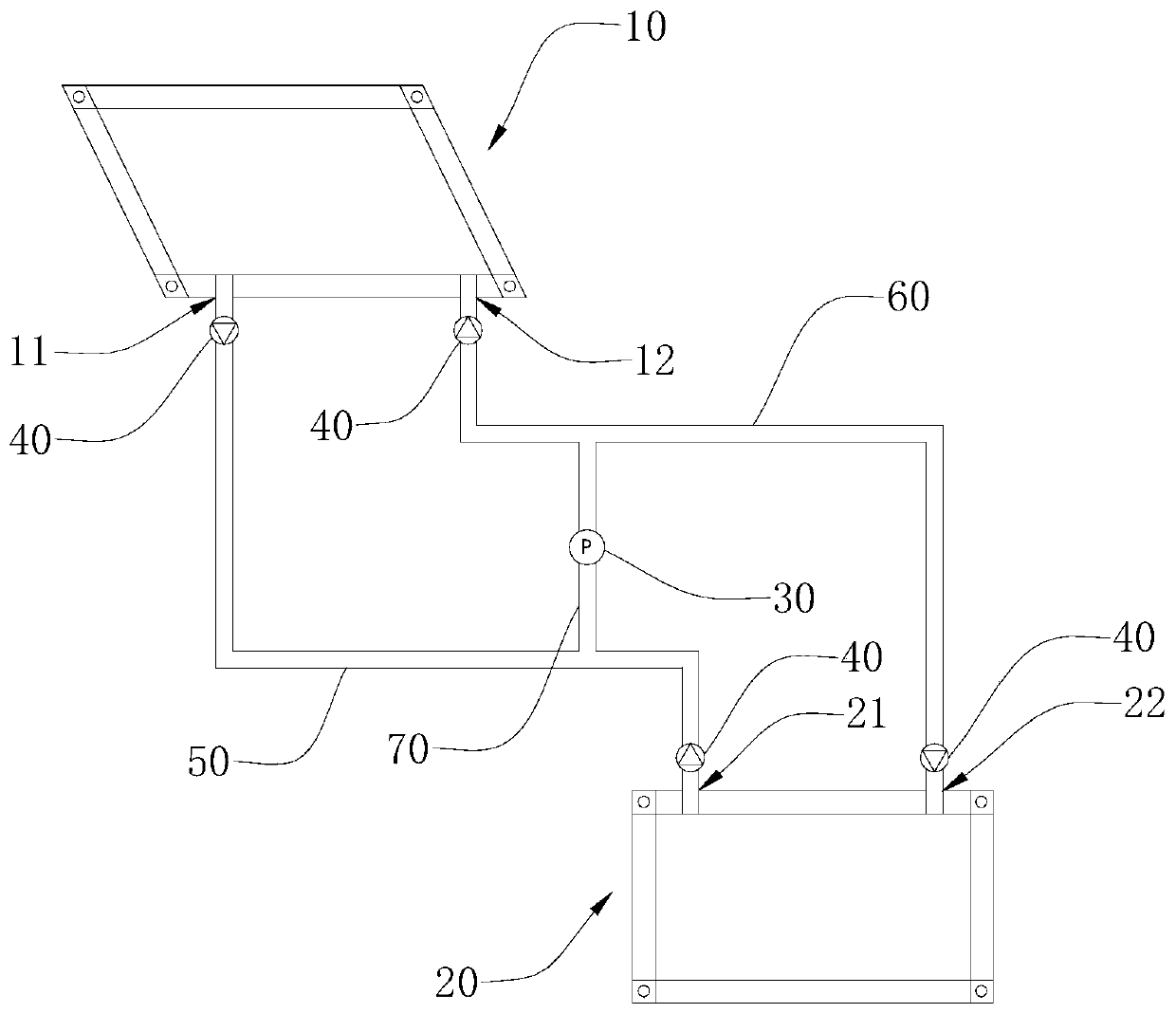
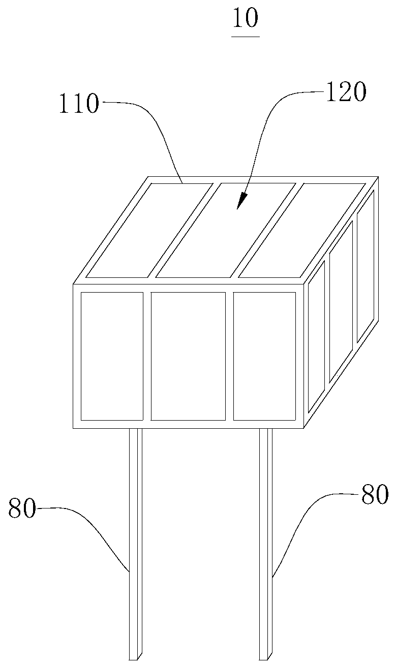
[0042] Please refer to figure 1 , an ocean wave energy conversion device, comprising: a first deformation assembly 10, a power generation device 30, and a second deformation assembly 20, which are all arranged near the sea and communicated in sequence. The first deformation assembly 10 and the second deformation assembly 20 are arranged alternately along the direction from the far sea to the coast, so that after the wave passes through the first deformation assembly 10 or the second deformation assembly 20, it can also be in the form of a complete wave and the second deformation assembly 20 or The first deformation component 10 is in contact. The power generation device 30 is located between the first deformation assembly 10 and the second deformation assembly 20 , and the power generation device 30 communicates with the first deformation assembly 10 and the second deformation assembly 20 respectively. Since the waves in the offshore are relatively regular, which is conducive...
Embodiment 2
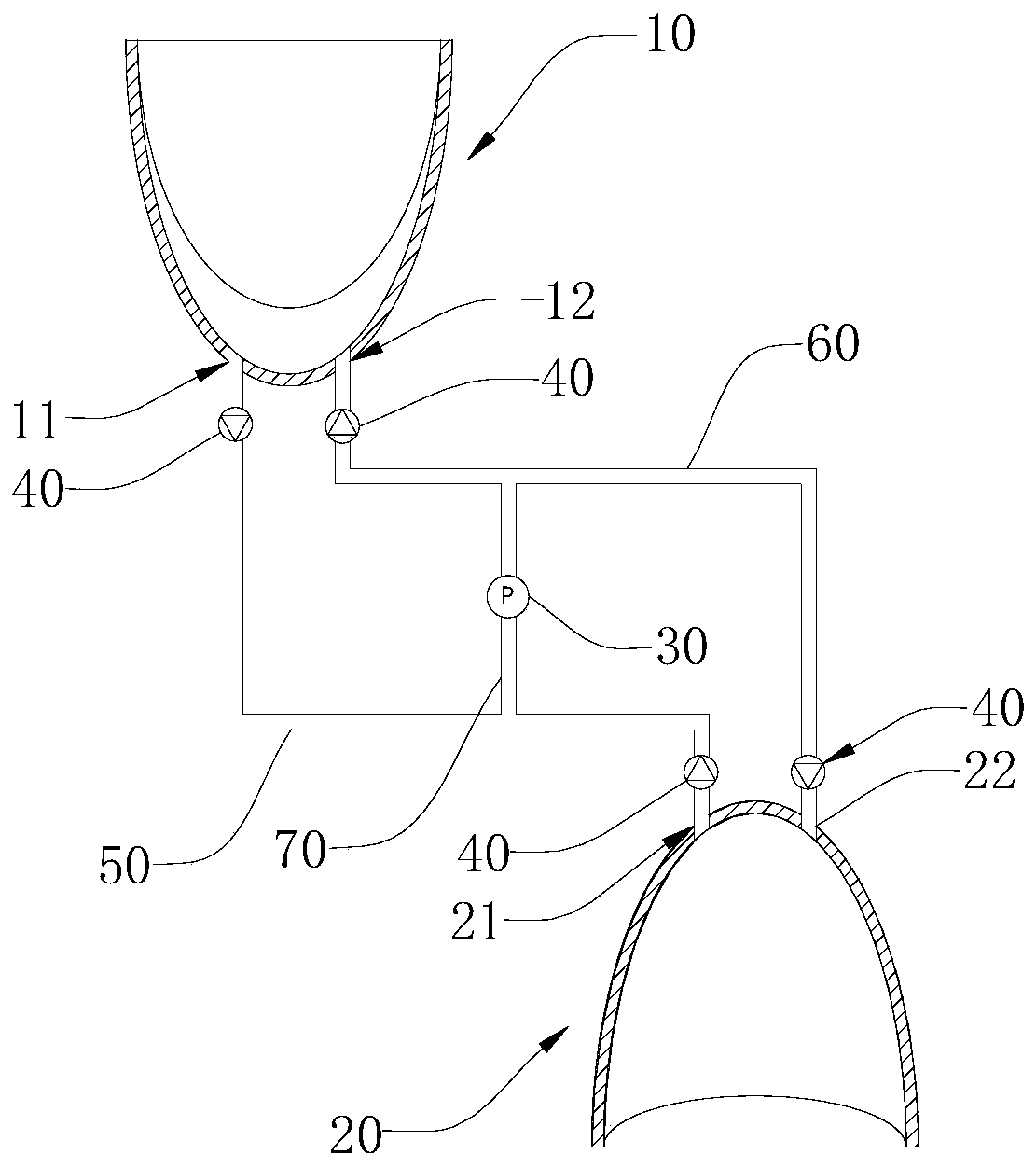
[0056] Please refer to image 3 and Figure 4 The difference between this embodiment and Embodiment 1 lies in that the structures of the first deformation assembly 10 and the second deformation assembly 20 are different. In this embodiment, the structures of the first deformation assembly 10 and the second deformation assembly 20 are consistent, and this embodiment only describes the structure of the first deformation assembly 10 .
[0057] The first deforming assembly 10 includes a fish mouth-shaped collecting piece 210 , one end of the collecting piece 210 is provided with an opening 220 , and the other end is provided with a first water outlet 11 and a first water inlet 12 . An elastic film 230 is provided at the opening 220, and the elastic film 230 is in sealing connection with the collection part 210. There is a deformation cavity between the elastic film 230 and the collection part 210. When the elastic film 230 is deformed, it will extend to the inner bottom of the co...
Embodiment 3
[0060] An ocean wave energy conversion method based on embodiment 1 or embodiment 2 ocean wave energy conversion device, is characterized in that, comprises the following steps:
[0061] S1: The first deformation component 10 is impacted and deformed by open sea waves, the fluid in the first deformation component 10 flows into the power generation device 30 from the first water outlet 11, the first pipeline 50 and the third pipeline 70 in sequence, and the wave energy is converted into kinetic energy of the fluid , the fluid flows through the power generation device 30 to drive the power generation device 30 to work, and the kinetic energy of the fluid is converted into electric energy;
[0062] S2: After the fluid in the first deformation assembly 10 flows through the power generation device 30, the fluid enters the second deformation assembly 20 from the third pipe 70, the second pipe 60 and the second water inlet 22 in sequence;
[0063] S3: The second deformation component...
PUM
 Abstract
Description
Claims
Application Information
 - R&D
- Intellectual Property
- Life Sciences
- Materials
- Tech Scout
- Unparalleled Data Quality
- Higher Quality Content
- 60% Fewer Hallucinations
Browse by: Latest US Patents, China's latest patents, Technical Efficacy Thesaurus, Application Domain, Technology Topic, Popular Technical Reports.
© 2025 PatSnap. All rights reserved.Legal|Privacy policy|Modern Slavery Act Transparency Statement|Sitemap|About US| Contact US: help@patsnap.com


