
Anti-collision sensor and welding robot

An anti-collision and sensor technology, applied in the field of sensors, can solve the problem that the anti-collision sensor cannot be reset automatically

Active Publication Date: 2017-05-31
江苏昌泓机器人科技有限公司
View PDF5 Cites 13 Cited by
  • Summary
  • Abstract
  • Description
  • Claims
  • Application Information

AI Technical Summary

Problems solved by technology

[0005] The purpose of the present invention is to provide an anti-collision sensor and a welding robot to solve the technical problem that the existing anti-collision sensor cannot be automatically reset during use

Method used


Image

  • Anti-collision sensor and welding robot
  • Anti-collision sensor and welding robot
  • Anti-collision sensor and welding robot

Examples


Embodiment 1

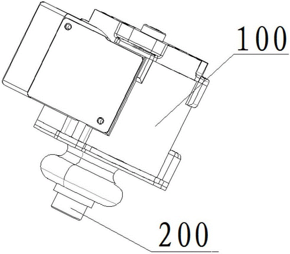
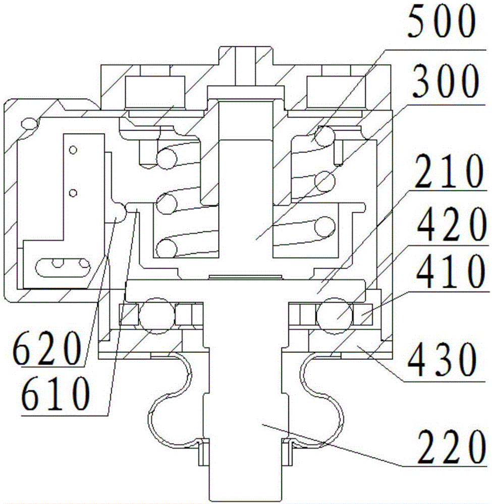
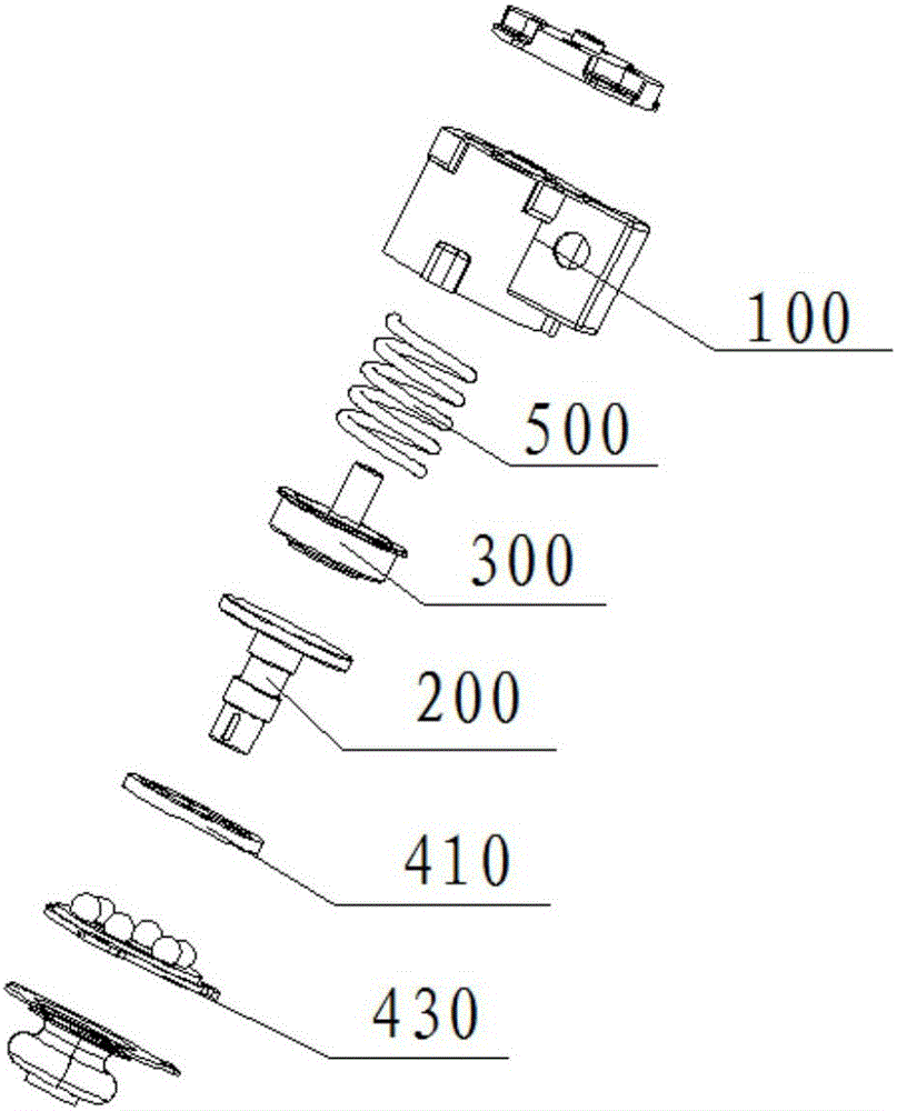
[0033]The anti-collision sensor provided by the present invention is connected to the movable working end, and includes: a casing 100, the opposite ends of the casing 100 are respectively slidably provided with a transmission part 200 and a sliding part 300, and the transmission part 200 is arranged on the sliding part 300 Between the movable working end and the movable working end, when the movable working end is hit by an external force, the transmission member 200 transmits the external force to the sliding member 300 to make the sliding member 300 slide relative to the housing 100 . The anti-collision sensor includes a sensing mechanism and a control mechanism. When the displacement of the slider 300 relative to the housing 100 exceeds a certain value, the control mechanism will stop the movement of the movable working end, thereby preventing the movable working end from being damaged due to collision. An elastic member is provided between the sliding member 300 and the inn...

Embodiment 2

[0047] The difference from Example 1 is that, as Figure 5 As shown, a plurality of wedge-shaped structures 810 and protrusions 820 are respectively provided on the opposite surface of the transmission plate 210 and the inner wall of the housing 100 , and the protrusions 820 abut against the slopes of the wedge-shaped structures 810 . Take the protrusion 820 on the rotating disk and the wedge-shaped structure 810 on the inner wall of the casing 100 as an example. When there is no collision, the protrusion 820 is located at the bottom of the wedge-shaped structure 810. When rotating force, the transmission shaft 220 will give a torque to the transmission disc 210, the protrusion 820 on the transmission disc 210 is limited by the wedge structure 810, the protrusion 820 can only move upward along the slope of the wedge structure 810, and then drive The sliding part 300 slides, so that the conversion of torsional displacement and linear displacement is realized. After the displace...


PUM


Abstract

The invention provides an anti-collision sensor and a welding robot, and relates to the technical field of sensors. The anti-collision sensor is connected with a movable work end. When the movable work end bears collision force, a transmission piece in the anti-collision sensor transmits the collision force to a sliding piece so that the sliding piece can slide relative to a shell. A control mechanism is used for stopping movement of the movable work end when a sensing mechanism senses that the displacement amount, relative to the shell, of the sliding piece reaches a preset value. An elastic piece is arranged between the sliding piece and the inner wall of the shell. After external force of the movable work end is removed, the elastic piece drives the sliding piece to slide to the balance position. The transmission piece comprises a transmission plate and a transmission shaft. A conversion assembly is arranged between the transmission plate and the inner wall of the shell so that the transmission plate can move in the sliding direction after the transmission shaft bears force not in the sliding direction and the anti-collision sensor can recognize collision force in various directions.

Description

technical field [0001] The invention relates to the technical field of sensors, in particular to an anti-collision sensor and a welding robot. Background technique [0002] With the rapid development of my country's machinery manufacturing industry and robot technology, more and more processing is required by robots, and the movements are becoming more and more complex. Using robots to perform operations not only greatly reduces labor costs, but also replaces manual labor for dangerous operations. For example, welding connection is a commonly used connection method for metal structures of mechanical equipment. There are many uncertain factors in manual welding. Therefore, welding robots used in welding operations have been widely used. [0003] However, due to irregular changes in the weld seam, it is easy to cause the welding torch to collide with the workpiece to be welded. The welding robot for automatic welding is usually driven by a servo motor, which has a high cost. If...

Claims


Application Information

Patent Timeline
IPC IPC(8): B23K37/02B25J11/00B25J19/02
CPCB23K37/02B25J11/00B25J19/02
Inventor 杨海燕杨俊
Owner 江苏昌泓机器人科技有限公司
Learn More