
A clamping device for automobile muffler and its hook

An automobile muffler and clamping device technology, applied in auxiliary devices, metal processing equipment, auxiliary welding equipment, etc., can solve the problems of welding deformation, inaccurate welding positioning, and low welding quality at the joints of elbows and special-shaped plates. Avoid shifting or loosening and ensure the effect of welding quality

Active Publication Date: 2019-04-30
景和智能制造(广东)有限公司
View PDF5 Cites 0 Cited by
  • Summary
  • Abstract
  • Description
  • Claims
  • Application Information

AI Technical Summary

Problems solved by technology

Although these bent pipes and special-shaped plates have great advantages in terms of structure and force, they also have inconveniences. When the joints of bent pipes and special-shaped plates need to be welded, due to their irregular shapes, general fixtures are difficult to weld. Fix the bent pipe and the shaped plate, which brings a lot of inconvenience to the welding between the bent pipe and the shaped plate
The welding positioning of the elbow and the special-shaped plate is inaccurate. If it is light, it may cause uneven welding force at the joint between the elbow and the special-shaped plate, and the welding quality is low. If it is serious, it may cause welding deformation at the joint between the elbow and the special-shaped plate.
[0004] Especially when assembling and welding the muffler body and the elbow hook connected to the muffler body, the side of the muffler body is a curved panel, and the end surface of the muffler body is a special-shaped curved panel, and the elbow hook is set on the end surface of the muffler body. , the existing fixture cannot clamp and fix the bent pipe and special-shaped plate, and the bent pipe and special-shaped plate will shift or loosen during the welding process, which makes welding difficult and often leads to welding deformation or low welding quality

Method used


Image

  • A clamping device for automobile muffler and its hook
  • A clamping device for automobile muffler and its hook
  • A clamping device for automobile muffler and its hook

Examples


Embodiment Construction

[0026] The clamping device of the present invention will be further described below in conjunction with the accompanying drawings and embodiments:

[0027] This embodiment provides a clamping device for an automobile muffler and its hook. The device is used for clamping the muffler and the hook connected to its body.

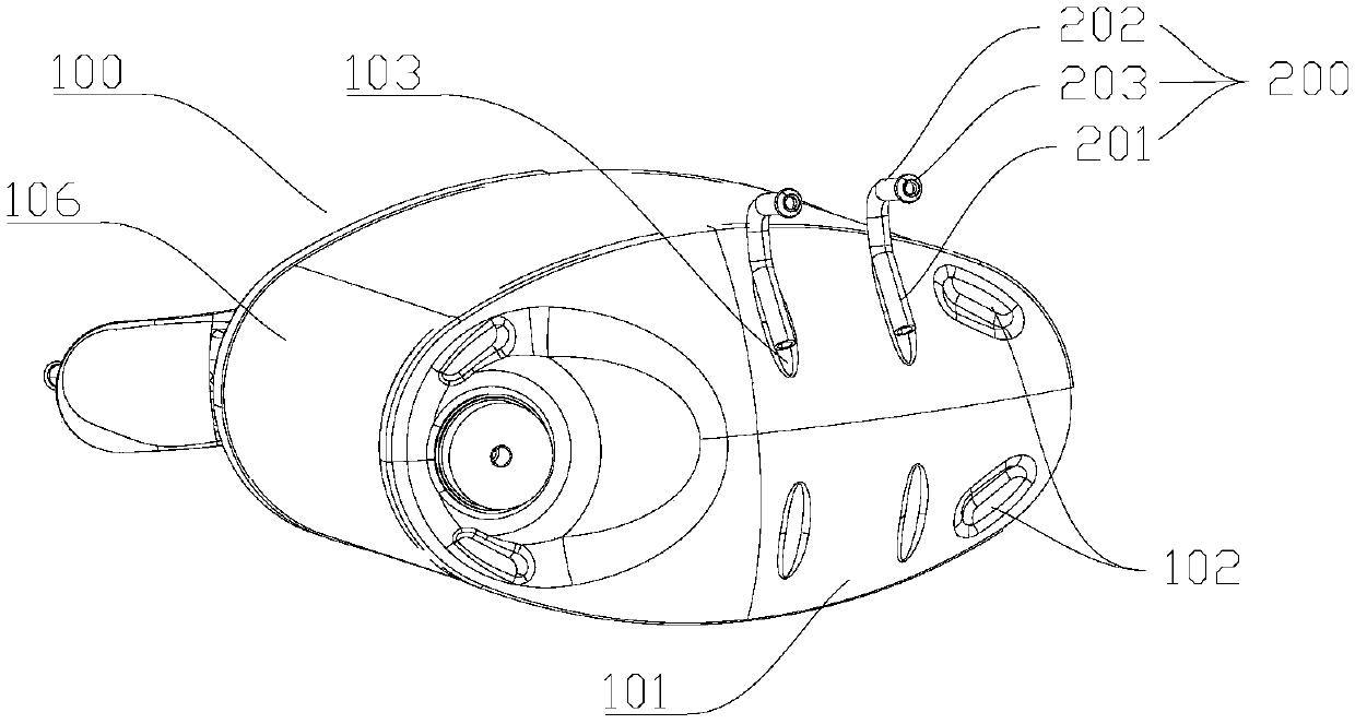
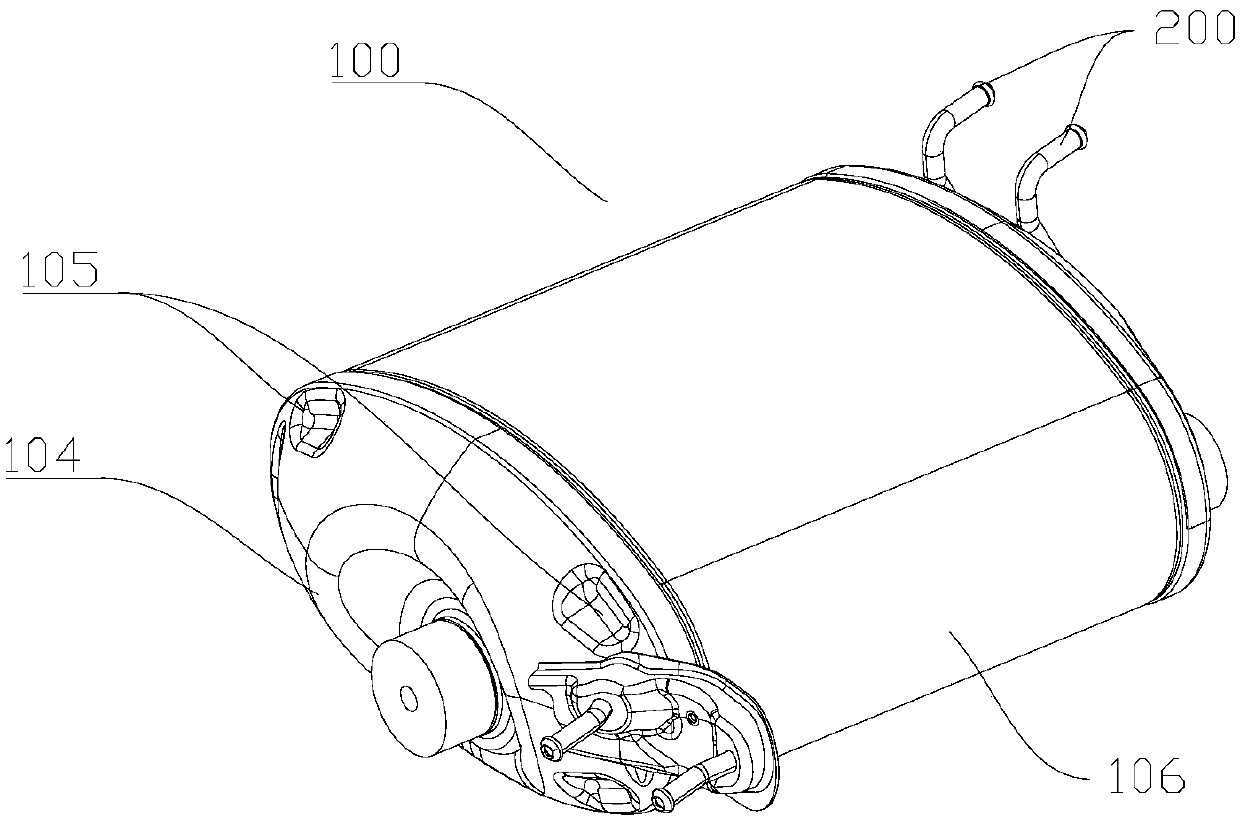
[0028] like figure 1 and figure 2 As shown, it is a structural schematic diagram of the muffler body 100 and its hook 200 . The muffler body 100 includes a muffler front surface 101 , a muffler rear surface 104 and a side surface 106 , and the muffler front surface 101 , the muffler rear surface 104 and the side surfaces 106 are arc-like surfaces. A recessed front groove 102 is provided near the edge of the muffler front surface 101 , and a hook installation groove 103 is also provided on the muffler front surface 101 . An indented rear end surface groove 105 is also provided near the edge of the muffler rear end surface 104 .

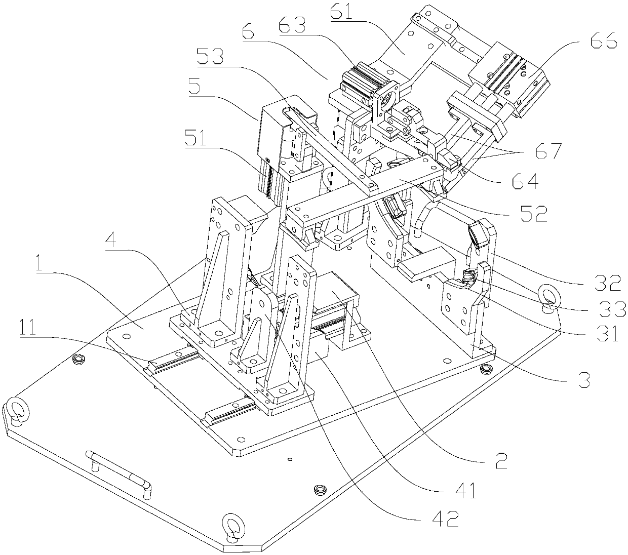
[0029] like image 3 , is a...


PUM


Abstract

The invention provides a clamping device used for an automobile silencer and a hook thereof. The clamping device structurally comprises a pedestal platform. The pedestal platform is provided with a silencer supporting base, a front silencer fixing base, a rear silencer fixing base and a hook fixing mechanism. The front silencer fixing base comprises a front clamping groove and a front baffle. The rear silencer fixing base comprises a rear clamping groove and a rear baffle. The front silencer fixing base and the rear silencer fixing base are used for clamping a silencer body in the horizontal direction together. The hook fixing mechanism at least comprises a hook groove, a second air cylinder and a second limiting block. The second limiting block is hinged to a piston rod of the second air cylinder and can be overturned up and down above the hook groove. By the adoption of the clamping device, the silencer body and the hook can be accurately fixed and positioned, and welding assembly quality is guaranteed.

Description

technical field [0001] The invention relates to an auxiliary equipment for assembly of automobile muffler accessories, in particular to a clamping device for the automobile muffler and its hook. Background technique [0002] With the development of society and the innovation of science and technology, the structure of automobiles is becoming more and more complex, and the performance of automobiles is getting better and better. The noise generated when the car is running is mainly the exhaust noise of the exhaust pipe, and the noise value can reach more than 100 decibels. Automobile mufflers are used to reduce the exhaust noise of the engine and enable the high-temperature exhaust gas to be discharged safely and effectively. Therefore, the effect of the automobile muffler is an important manifestation of the high-quality performance of the automobile. The direct assembly and welding quality of the muffler and the exhaust pipe will directly affect the effect of the muffler ...

Claims


Application Information

Patent Timeline
Patent Type & Authority Patents(China)
IPC IPC(8): B23K37/04
CPCB23K37/0435
Inventor 伍朝砖
Owner 景和智能制造(广东)有限公司
Learn More