A method of calibrating the distance between axes

A calibration method and a technology of axial spacing, which is applied in the mechanical field, can solve problems affecting machining accuracy, achieve the effect of improving machining performance and solving machining accuracy problems

Active Publication Date: 2019-05-10
HANS CNC SCI & TECH
View PDF6 Cites 0 Cited by
  • Summary
  • Abstract
  • Description
  • Claims
  • Application Information

AI Technical Summary

Problems solved by technology

Due to the thermal expansion of the mechanical structure and the workpiece, the distance between the two axes will definitely change after a period of time. If it is not adjusted in time, it will affect the machining accuracy.

Method used


Image

  • A method of calibrating the distance between axes
  • A method of calibrating the distance between axes
  • A method of calibrating the distance between axes

Examples


Embodiment Construction

[0023] In order to make the object, technical solution and advantages of the present invention clearer, the present invention will be further described in detail below in conjunction with the accompanying drawings and embodiments. It should be understood that the specific embodiments described here are only used to explain the present invention, not to limit the present invention.

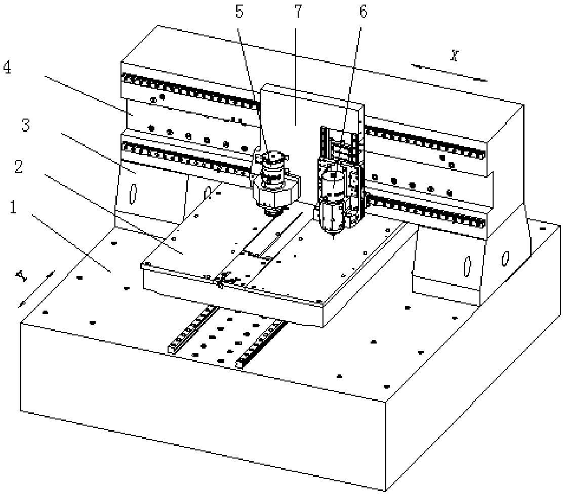
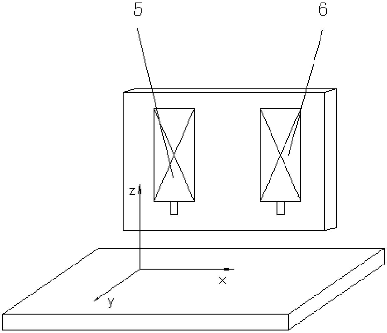
[0024] figure 1 A drilling and gong dual-purpose machine applied in the embodiment of the present invention is shown, which includes a bed 1 , a worktable 2 , a beam base 3 , a beam 4 , a drill shaft 5 , a gong shaft 6 and a bottom plate 7 . The main body of the machine adopts a gantry structure, and the X and Y axes are separated and independent. The drill shaft 5 and the gong shaft 6 are installed in the X-axis direction. The drill shaft 5 and the gong shaft 6 are driven by the same motor in the X-axis direction. position is provided by the same feedback system.

[0025] Before the circuit boar...


PUM


Abstract

The invention relates to the mechanical field, in particular to a shaft distance calibrating method. The method comprises the following steps that 1, a drilling shaft or a threading shaft of a drilling-threading machine is selected as a coordinate reference shaft, and machining files of three holes are written, wherein the machine coordinate of the first hole is (0,0), any X and Y machine coordinate of the second hole accords with the corresponding coordinate of the first hole, and the machine coordinate of the third hole is an any value; 2, the first hole and the second hole are machined on a circuit board through a reference shaft of the drilling-threading machine, and the third hole in machined on the circuit board through the other shaft; 3, the actual coordinate value of the third hole in the circuit board is detected through quadratic element detection equipment; and 4, according to the difference value between the machine coordinate of the third hole and the actual coordinate, the shaft distance between the two shafts of the drilling-threading machine is calculated. The shaft distance calibrating method is easy and practical, the machining precision problem caused by deformation caused by thermal expansion of workpieces and a mechanical structure is solved, and equipment machining performance is improved.

Description

technical field [0001] The invention relates to the mechanical field, in particular to a method for calibrating the distance between axes. Background technique [0002] Since circuit board manufacturers need proofing, proofing requires the use of drilling rigs and gong machines for drilling and forming respectively. In order to save time for proofing, a dual-purpose drilling and gong machine that can complete drilling and forming on the same machine came into being. The use of drilling and gong dual-purpose machines for proofing can not only reduce the time for panel installation, disassembly and repositioning, but also save equipment investment. [0003] figure 1 It is a schematic diagram of the structure of the drilling and gong dual-purpose machine. Its main body adopts a gantry structure, and the X and Y axes are separated and independent. The drill shaft and the gong shaft are installed in the X-axis direction; Driven by a motor, the positions of the two axes are pro...

Claims


Application Information

Patent Timeline
Patent Type & Authority Patents(China)
IPC IPC(8): B23Q3/18B23B49/00
CPCB23B49/00B23Q3/186
Inventor 蔡小丽陈献华翟学涛杨朝辉高云峰
Owner HANS CNC SCI & TECH
Why Eureka
Try Eureka