A multi-station automatic loading and unloading processing equipment

A technology of automatic loading and unloading, processing equipment, applied in metal processing equipment, metal processing, metal processing machinery parts and other directions, can solve the problems of processing equipment can not automatically load and unload, each station can not be connected in series, low work efficiency, etc. The effect of saving labor cost, simple and ingenious structure, and high work efficiency

Active Publication Date: 2018-12-14
山东辛丁管理咨询有限公司
View PDF11 Cites 0 Cited by
  • Summary
  • Abstract
  • Description
  • Claims
  • Application Information

AI Technical Summary

Problems solved by technology

[0007] The purpose of the present invention is to provide a multi-station automatic loading and unloading processing equipment for the deficiencies of the prior art, which overcomes the inability of the processing equipment to automatically load and unload materials, and the inability of each station to be connected in series, resulting in low work efficiency, time-consuming and manpower-consuming The problem

Method used


Image

  • A multi-station automatic loading and unloading processing equipment
  • A multi-station automatic loading and unloading processing equipment
  • A multi-station automatic loading and unloading processing equipment

Examples


Embodiment 1

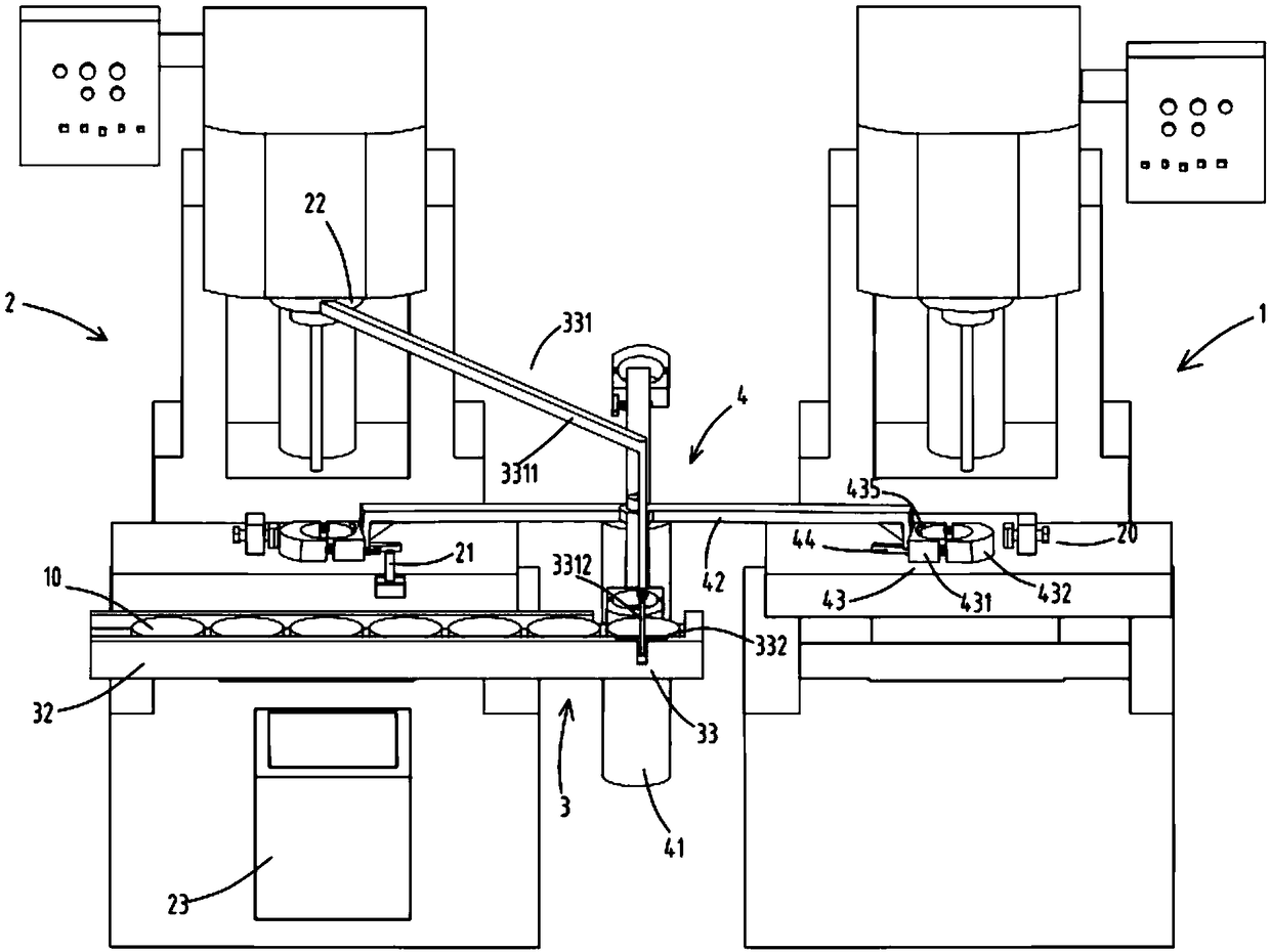
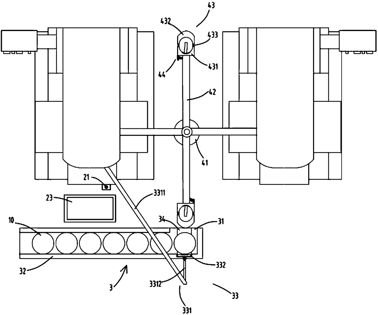
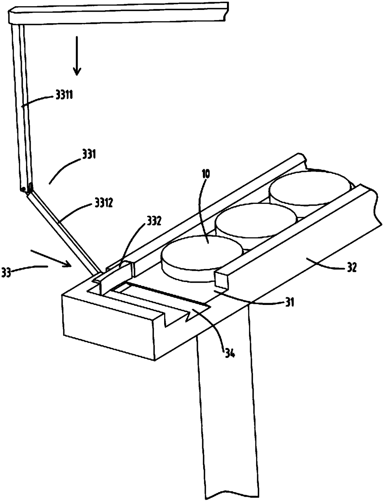
[0035] figure 1 It is a schematic diagram of multi-station automatic loading and unloading processing equipment, figure 2 It is a top view schematic diagram of multi-station automatic loading and unloading processing equipment, image 3 It is a schematic diagram of the structure of the feeding equipment, Figure 4 It is a partial structural schematic diagram of the feeding device, Figure 5 It is a schematic diagram of the pressing device when pressing the clamping device. Such as figure 1 , figure 2 , image 3 , Figure 4 and Figure 5 As shown, what is provided in this embodiment is a multi-station automatic loading and unloading processing equipment, including

[0036] The processing equipment a1 is used to process the workpiece 10 in the first process;

[0037] The processing equipment b2 is used to process the workpiece 10 in the second process;

[0038] It should be noted that the processing equipment a1 and the processing equipment b2 are only set for this e...

Embodiment 2

[0052] Such as figure 1 , figure 2 , image 3 , Figure 4 , Figure 5 As shown, the components that are the same as or corresponding to those in the first embodiment are marked with the corresponding reference numerals in the first embodiment. For the sake of simplicity, only the differences from the first embodiment will be described below. The difference between the second embodiment and the first embodiment is that a guide rod 434 is also provided between the fixed clamp block 431 and the movable clamp block 432, one end of the guide rod 434 is fixed on the fixed clamp block 431, and the other end is relatively movable. The guide groove 4321 provided on the clamp block 432 slides; the elastic member 433 is sleeved on the guide rod 434, and the guide rod 434 guides the movement of the movable clamp block 432, preventing the movable clamp block 432 from being squeezed and A large offset angle affects the effect of clamping.

[0053] Working process: multiple material ar...


PUM


Abstract

The invention relates to multi-station automatic feeding and discharging machining equipment. The multi-station automatic feeding and discharging machining equipment comprises a machining unit a, a machining unit b, a supplying unit and a feeding unit, wherein the machining unit a is used for carrying out a first procedure of machining on workpieces; the machining unit b is used for carrying out a second procedure of machining on the workpieces; the supplying unit comprises a conveying device and a pushing device, a discharging port is formed in the tail portion of the conveying device, and the pushing device is arranged at the tail portion of the conveying device; the pushing device comprises a transmission part and a push block capable of sliding front and back along a sliding groove in the tail portion of the conveying device under driving of the transmission part; and the feeding unit is used for bearing the workpieces pushed by the pushing device from the conveying device to the feeding device, and comprises a rotary device, a plurality of material arms, clamping devices and supporting devices, one ends of the material arms are fixed on the rotary device, the clamping devices are fixed at the ends of the material arms, and the supporting devices are rotationally arranged at the bottoms of the clamping devices. By means of the multi-station automatic feeding and discharging machining equipment, the problems that machining equipment cannot achieve automatic feeding or discharging, various stations cannot be connected in series, working efficiency is low, and time and labor are wasted are solved.

Description

technical field [0001] The invention belongs to the technical field of machining equipment, in particular to a multi-station automatic loading and unloading processing equipment. Background technique [0002] Existing processing equipment generally requires manual loading and operation of the fixture to clamp the workpiece and then start the equipment to start processing. After processing, loosen the fixture and then take out the processed workpiece. The efficiency is low and the process of taking the workpiece is easy to be wasted. Chips slip and hurt hands. In addition, when a single workpiece needs to be processed in multiple processes, it can only be processed at one station and then transported to the next station and then manually loaded one by one. It is time-consuming and labor-intensive. Therefore, it is necessary to design a Automatic loading and unloading equipment that can simultaneously load and unload multiple stations to improve work efficiency and save manpow...

Claims


Application Information

Patent Timeline
Patent Type & Authority Patents(China)
IPC IPC(8): B23Q7/00B23Q3/06
CPCB23Q3/06B23Q7/00B23Q7/006
Inventor 徐臻
Owner 山东辛丁管理咨询有限公司
Why Eureka
Try Eureka