
Clamping mechanism

A clamping mechanism and clamping jaw technology, applied in the direction of chuck, manipulator, program-controlled manipulator, etc., can solve the problems of high cost and complicated structure of clamping mechanism, and achieve the effect of low cost, compact structure and simple structure

Inactive Publication Date: 2017-05-31
王安基
View PDF0 Cites 7 Cited by
  • Summary
  • Abstract
  • Description
  • Claims
  • Application Information

AI Technical Summary

Problems solved by technology

[0003] The purpose of the present invention is to provide a clamping mechanism to alleviate the technical problems of complex structure and high cost of the clamping mechanism in the prior art

Method used


Image

  • Clamping mechanism
  • Clamping mechanism
  • Clamping mechanism

Examples


Embodiment 1

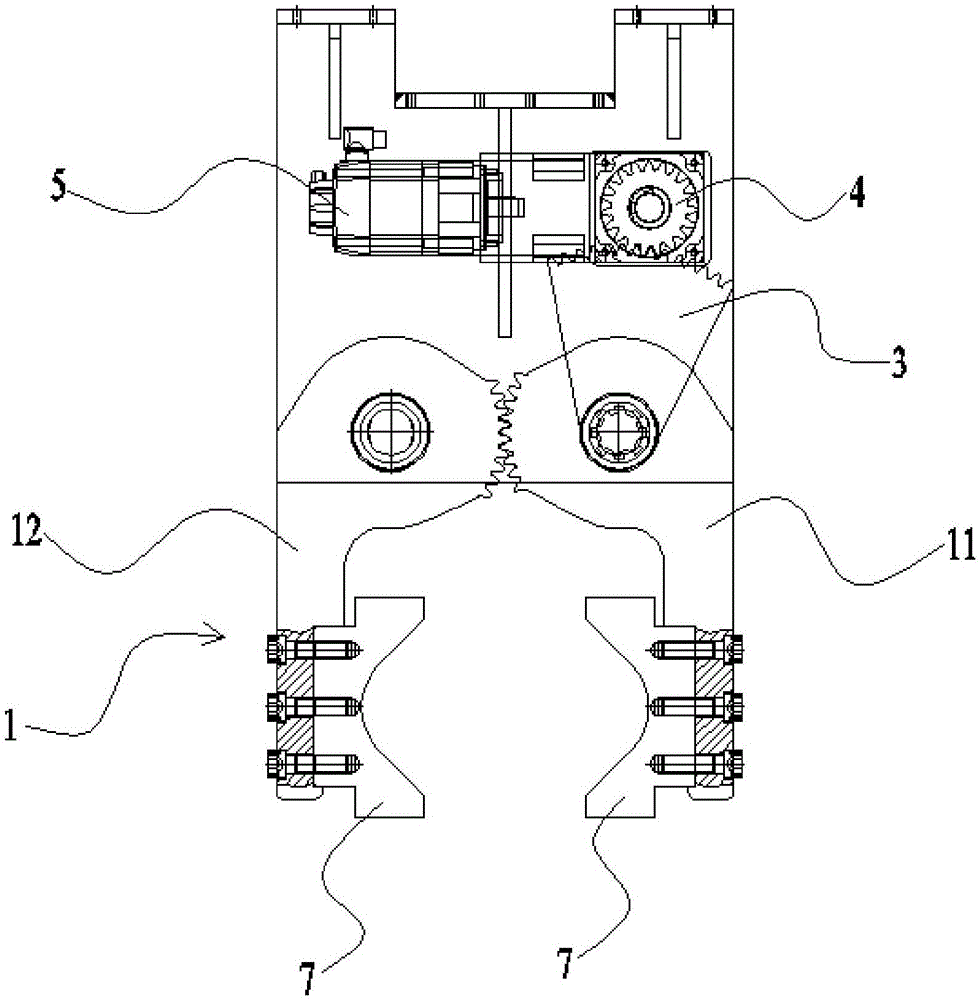
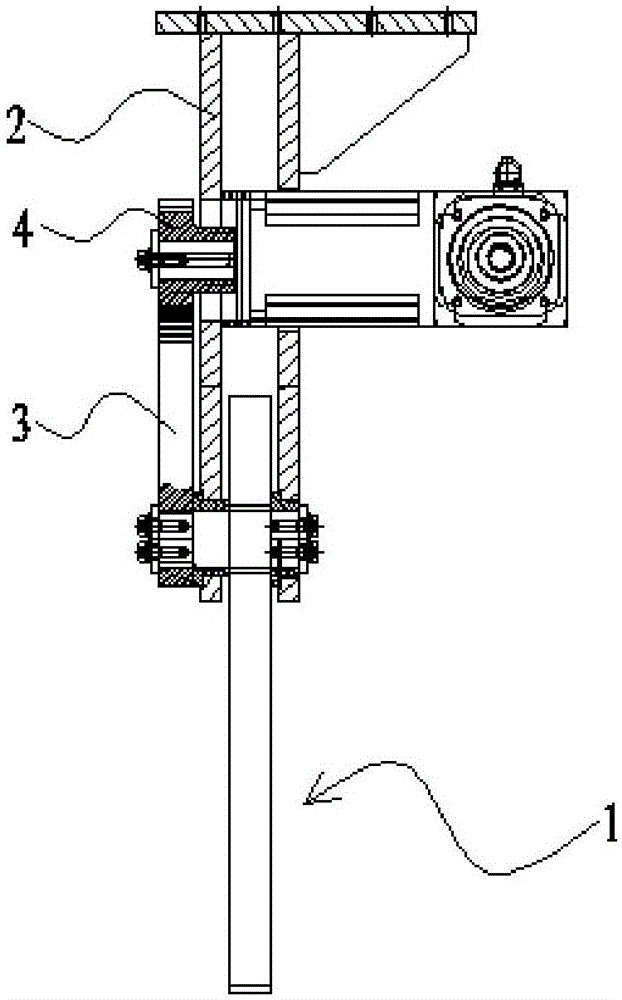
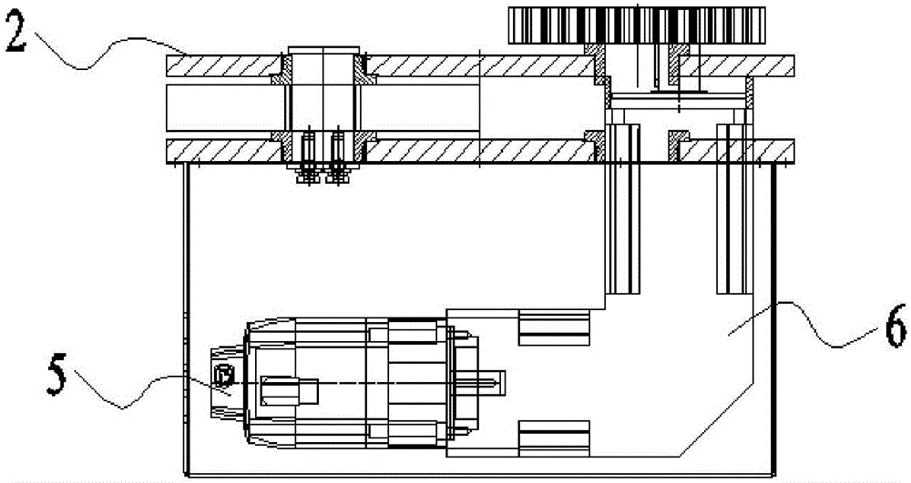
[0033] Such as figure 1 As shown in -3, the clamping mechanism provided by this embodiment includes: jaw 1, which is composed of a master arm 11 and a slave arm 12 arranged oppositely; the master arm 11 and the slave arm 12 both include clamping part and the transmission part, and are pivotally connected to the base 2 through the respective transmission parts; the transmission parts are at least partially arc-shaped, the transmission part arc part of the driving arm 11 is provided with active teeth, and the transmission part arc part of the driven arm 12 is The shaped part is provided with a driven tooth capable of meshing with the driving tooth, and the driving arm 11 and the driven arm 12 are engaged for transmission; the driving arm 11 is connected with a power unit for driving it to rotate.

[0034] When working, the driving arm is driven by the power unit to pivot relative to the base, and the driving tooth on the driving arm meshes with the driven tooth on the driven arm...

Embodiment 2

[0059] Another clamping mechanism provided by the present invention includes: a clamping jaw 1 and a power unit, the clamping jaw 1 is composed of a driving arm 11 and a driven arm 12 arranged oppositely,

[0060] Both the active arm 11 and the driven arm 12 include a clamping portion and a transmission portion, and are pivotally connected to the base 2 through respective transmission portions; the transmission portions are at least partially arc-shaped, and the arc portion of the transmission portion of the active arm 11 is set There are active teeth, and the arc-shaped part of the transmission part of the driven arm 12 is provided with driven teeth that can mesh with the active teeth, and the meshing transmission between the active arm 11 and the driven arm 12; the power unit includes a servo motor and a transmission assembly, and the transmission assembly It includes a first gear 3 fixed on the transmission part of the active arm 11 and a second gear 4 meshing with the first...


PUM


Abstract

The invention provides a clamping mechanism, and relates to the technical field of clamping devices. The clamping mechanism comprises a clamping jaw which is composed of a driving arm and a driven arm, and the driving arm and the driven arm are oppositely arranged. The driving arm and the driven arm each comprise a clamping part and a transmission part, and the driving arm and the driven arm are pivoted on a base through the respective transmission parts. At least a part of each transmission part is arc, the arc portion of the transmission part of the driving arm is provided with driving teeth, and the arc portion of the transmission part of the driven arm is provided with driven teeth capable of being engaged with the driving teeth. The driving arm and the driven arm are in engaged transmission. The driving arm is connected with a power unit for driving the driving arm to rotate. The clamping mechanism is used for solving the technical problems that in the prior art, a clamping mechanism is complex in structure and high in cost.

Description

technical field [0001] The invention relates to the technical field of clamping devices, in particular to a clamping mechanism. Background technique [0002] The clamping mechanism is widely used in various equipments for material transfer or positioning. However, in the prior art, the structure of the clamping mechanism is usually relatively complicated and the cost is high, which does not meet the requirements of simplifying the structure and saving costs. Therefore, it is very necessary to design a new clamping mechanism to alleviate the above technical problems. Contents of the invention [0003] The object of the present invention is to provide a clamping mechanism to alleviate the technical problems of complex structure and high cost of the clamping mechanism in the prior art. [0004] The clamping mechanism provided by the present invention includes: a clamping jaw, the clamping jaw is composed of a driving arm and a driven arm oppositely arranged; the driving arm...

Claims


Application Information

Patent Timeline
IPC IPC(8): B25J15/02B25J9/16
CPCB25J15/02B25J9/1633
Inventor 王安基
Owner 王安基
Learn More