Wood cutting machine

A cutting machine and wood technology, which is applied in the direction of wood processing equipment, sawing components, sawing equipment, etc., can solve the problems of inaccurate cutting line, deviation of wood cutting line, and manual injury, so as to facilitate manual control and cutting The effect of smooth surface and precise wiring

Inactive Publication Date: 2017-05-31
龚梁涛
View PDF11 Cites 6 Cited by
  • Summary
  • Abstract
  • Description
  • Claims
  • Application Information

AI Technical Summary

Problems solved by technology

[0002] The traditional wood cutting machine needs to manually control the wood when cutting, but the manual control of the wood will cause unstable control of the wood, causing hand abrasions during the cutting process, and secondly, it will cause the wood cutting line to deviate, and the wood cutting surface will not be sm

Method used


Image

  • Wood cutting machine
  • Wood cutting machine

Examples


Embodiment 1

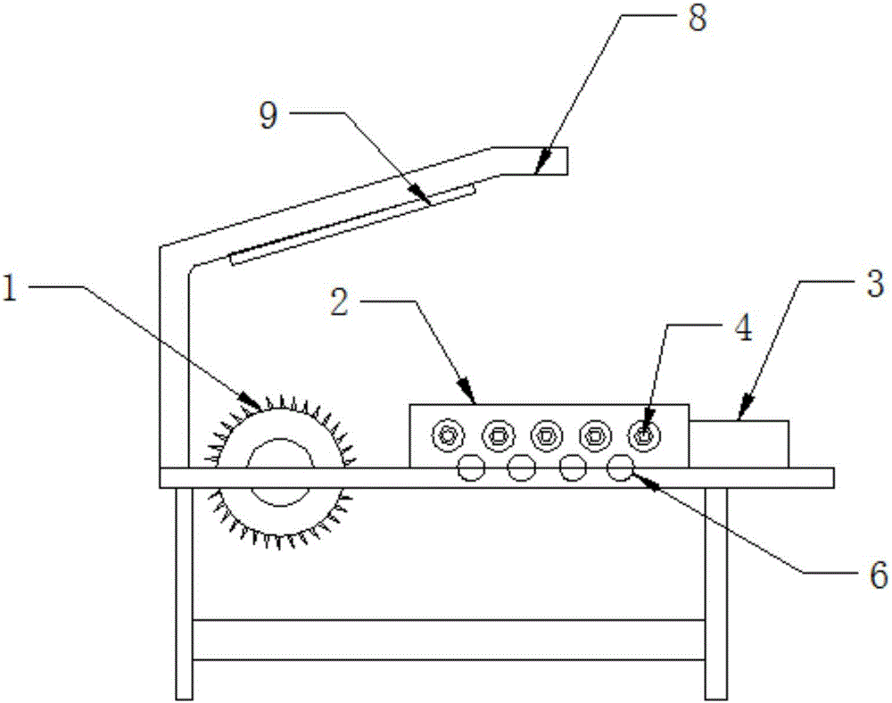
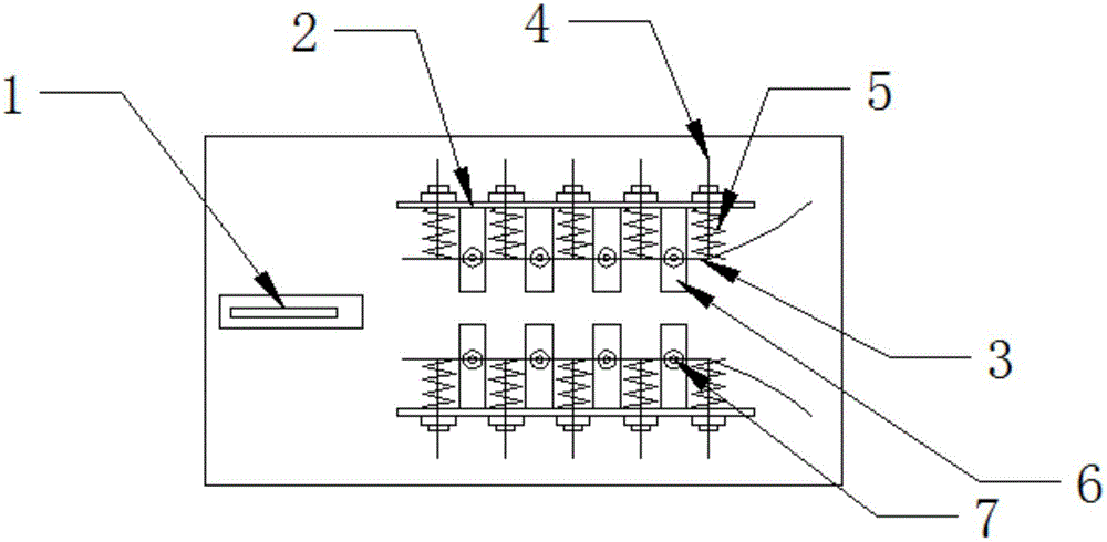
[0023] Such as figure 1 and figure 2 As shown, a wood cutting machine includes a cutting table and a saw blade 1 vertically installed on the cutting table. Two baffle plates 2 are fixedly arranged, and the two baffle plates 2 are arranged symmetrically in parallel. The saw blade 1 is installed on the front ends of the symmetrical line of the two baffle plates 2 , and the sides of the two baffle plates 2 are provided with a plurality of holes for the vertical penetration of the screw rod 4 . hole, the screw 4 can slide in the through hole, the screw 4 is sleeved with a spring 5 on the inner side of the baffle, and the screw 4 is fixedly connected to the flexible steel plate 3 at the inner side of the baffle 2; A rolling bearing 7 is horizontally arranged on the steel plate 3, and the spring 5 is in a natural state. One end of the spring 5 is fixedly connected to the flexible steel plate 3, and the other end is against the inner side of the baffle plate 2; A roller 6 is arran...

Embodiment 2

[0026] Such as figure 1 and figure 2 As shown, a wood cutting machine includes a cutting table and a saw blade 1 vertically installed on the cutting table. Two baffle plates 2 are fixedly arranged, and the two baffle plates 2 are arranged symmetrically in parallel. The saw blade 1 is installed on the front ends of the symmetrical line of the two baffle plates 2 , and the sides of the two baffle plates 2 are provided with a plurality of holes for the vertical penetration of the screw rod 4 . hole, the screw 4 can slide in the through hole, the screw 4 is sleeved with a spring 5 on the inner side of the baffle, and the screw 4 is fixedly connected to the flexible steel plate 3 at the inner side of the baffle 2; A rolling bearing 7 is horizontally arranged on the steel plate 3, and the spring 5 is in a natural state. One end of the spring 5 is fixedly connected to the flexible steel plate 3, and the other end is against the inner side of the baffle plate 2; A roller 6 is arran...

Embodiment 3

[0029] Such as figure 1 and figure 2 As shown, a wood cutting machine includes a cutting table and a saw blade 1 vertically installed on the cutting table. Two baffle plates 2 are fixedly arranged, and the two baffle plates 2 are arranged symmetrically in parallel. The saw blade 1 is installed on the front ends of the symmetrical line of the two baffle plates 2 , and the sides of the two baffle plates 2 are provided with a plurality of holes for the vertical penetration of the screw rod 4 . hole, the screw 4 can slide in the through hole, the screw 4 is sleeved with a spring 5 on the inner side of the baffle, and the screw 4 is fixedly connected to the flexible steel plate 3 at the inner side of the baffle 2; A rolling bearing 7 is horizontally arranged on the steel plate 3, and the spring 5 is in a natural state. One end of the spring 5 is fixedly connected to the flexible steel plate 3, and the other end is against the inner side of the baffle plate 2; A roller 6 is arran...


PUM

PropertyMeasurementUnit
Wire diameteraaaaaaaaaa
Diameteraaaaaaaaaa

Abstract

The invention discloses a wood cutting machine which comprises a cutting table and a saw blade perpendicularly installed on the cutting table. The wood cutting machine is characterized by comprising baffles, flexible steel plates and multiple screw rods, the two baffles are perpendicularly and fixedly arranged on the working plane of the cutting table, the two baffles are symmetrically arranged in parallel, the saw blade is installed at the front end of the symmetrical line of the two baffles, the side faces of the two baffles are provided with multiple through holes allowing the screw rods to perpendicularly penetrate therein, the screw rods can slide in the through holes, the sections, on the inner sides of the baffles, of the screw rods are sleeved with springs, and the ends, on the inner sides of the baffles, of the screw rods are fixedly connected with the flexible steel plates. Rolling bearings are horizontally arranged on the flexible steel plates. In the natural state of the springs, one ends of the springs are fixedly connected with the flexible steel plates, and the other ends of the springs abut against the inner sides of the baffles. Rollers perpendicular to the baffles are arranged in the portion, between the two baffles, in the working plane of the cutting table.

Description

technical field [0001] The invention relates to a wood cutting machine, in particular to a wood cutting machine. Background technique [0002] The traditional wood cutting machine needs to manually control the wood when cutting, but the manual control of the wood will cause unstable control of the wood, causing hand abrasions during the cutting process, and secondly, it will cause the wood cutting line to deviate, and the wood cutting surface will not be smooth. leveling issues. [0003] For example, a wood cutting machine disclosed in the patent No. CN201520211521.1 requires manual control of the wood during processing, which is likely to cause injuries to the hands during the cutting process, and the cutting line is not accurate, and the cutting surface is not smooth. Contents of the invention [0004] Based on this, in view of the above problems, it is necessary to propose a wood cutting machine, which can effectively stabilize the wood, reduce the shaking of the wood,...

Claims


Application Information

Patent Timeline
IPC IPC(8): B27B5/22B27B5/29B27B25/00
CPCB27B5/222B27B5/29B27B25/00
Inventor 龚梁涛
Owner 龚梁涛
Why Eureka
Try Eureka