
Emergency parachute landing device for multi-rotor unmanned aerial vehicle

A multi-rotor unmanned aerial vehicle and emergency parachute technology, which is applied in the direction of unmanned aircraft, emergency equipment, motor vehicles, etc., can solve the problems of not being able to meet the requirements of low altitude, oblique launching structure, large footprint, and low service life. Achieve long packaging and storage life, facilitate long-term storage, and improve reliability

Pending Publication Date: 2017-05-31
HUBEI DERUI SITONG TECH
View PDF7 Cites 14 Cited by
  • Summary
  • Abstract
  • Description
  • Claims
  • Application Information

AI Technical Summary

Problems solved by technology

[0007] 1) The existing technology can only throw out the "parachute cluster" in the folded state, and the parachute needs to go through the process of straightening, inflating, and full expansion, and the multi-rotor UAV generally has no horizontal speed when it fails, so its deployment The process depends entirely on the speed generated when the faulty UAV falls, and the parachute will lose a lot of height when opening the parachute, which cannot meet the emergency parachute opening under conditions such as low altitude, low speed, and unfavorable attitude;
[0008] 2) In the existing technology, after the parachute is thrown out of the umbrella cabin, the parachute opening process is long and uncontrolled, and it is easy to be entangled with the propeller and body of the UAV, and the safety of its parachute opening is low;
[0009] 3) In the spring structure, the locking mechanism after the spring is compressed is complicated, and the initial velocity provided by the spring is limited, so it is difficult to throw the parachute a sufficient distance, which makes the parachute easily entangled with the drone, and its safety is low;
[0010] 4) When the spring structure is not in use, the spring is always under stress, so its service life is low;
[0011] 5) There are many structural components in the umbrella barrel scheme, and the oblique launch structure occupies a large volume, which has poor applicability and high cost of the structure

Method used


Image

  • Emergency parachute landing device for multi-rotor unmanned aerial vehicle
  • Emergency parachute landing device for multi-rotor unmanned aerial vehicle

Examples


Embodiment Construction

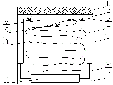
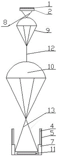
[0032] figure 1 , 2 Among them, the present invention consists of an umbrella cabin 5, an umbrella cabin cover 2, an umbrella cabin cover crash pad 1, a guiding umbrella connecting belt 8, a guiding umbrella 9, a main umbrella connecting belt 12, a main umbrella 10, a main sling 13, and an umbrella opener 4 , Umbrella opener mount 7, controller 11 forms. Umbrella cabin 5 is divided into two layers up and down, and the upper strata is used for installing parachute parts such as guide parachute 9, guide parachute connecting band 8, main parachute 10, main parachute connecting band 12 and main suspension belt 13, and lower floor is used for installing controller 11. The canopy cover 2 is used to seal the canopy 5, and is ejected after the parachute opener 4 is excited and separated from the canopy 5, so as to pull out and straighten the various parts of the parachute. Umbrella canopy 2 is connected with umbrella opener 4 by screw 3, and umbrella canopy 2 is fixed to umbrella ca...


PUM


Abstract

Provided is an emergency parachute landing gear for a multi-rotor unmanned aerial vehicle. The device comprises a parachute cabin, a parachute cabin cover and an open-parachute-device, the opening of the upper end of the parachute cabin is provided with the parachute cabin cover, a folded parachute is arranged in the parachute cabin, the top of the parachute is connected to the parachute cabin cover, and the open-parachute-device is arranged in the parachute cabin, and is used for pushing the parachute cabin cover to be separated from the parachute cabin so as to drive the folded parachute to be pulled out of the parachute cabin and straightened. The emergency parachute landing gear for the multi-rotor unmanned aerial vehicle can directly pull out and straighten the parachute, and is suitable for various parachute cabin shapes, the parachute opening reliability is high, the safety is high, and the cost is low.

Description

technical field [0001] The invention relates to a parachute device, which belongs to the technical field of unmanned aerial vehicle recovery, and is suitable for safe parachute landing recovery of various multi-rotor unmanned aerial vehicles. Background technique [0002] Multi-rotor UAVs will fall quickly after failures such as loss of control and stall, thereby injuring ground personnel and buildings. With the application and promotion of multi-rotor UAVs, the probability of the above accidents will greatly increase. When the multi-rotor UAV fails, a parachute is generally used to open a parachute in the air to reduce its falling speed and ensure the safety of ground personnel and buildings. [0003] Chinese patent "An emergency parachute device and method for multi-rotor UAV" (publication number: CN103895870 A, publication date: 2014.07.02) discloses an emergency parachute device and method, which includes a The measurement and control unit, unlocking steering gear, para...

Claims


Application Information

Patent Timeline
IPC IPC(8): B64D17/80B64D17/64B64D17/76B64D17/54
CPCB64D17/54B64D17/64B64D17/76B64D17/80B64U10/10B64U70/83
Inventor 王文凯
Owner HUBEI DERUI SITONG TECH
Learn More