Bin sweeping machine and bin

A silo and cylinder technology, applied in the field of sweeping machines and silos, can solve problems such as inability to flow out, difficult flow out, slow speed, etc., and achieve the effect of preventing bridge formation

Active Publication Date: 2017-05-31
溧阳市金诺机械有限公司
View PDF6 Cites 9 Cited by
  • Summary
  • Abstract
  • Description
  • Claims
  • Application Information

AI Technical Summary

Problems solved by technology

[0002] If the powdery or granular materials in the silo flow out naturally, the speed is slow, and the materials are easy to bridge and arch and cannot...

Method used


Image

  • Bin sweeping machine and bin
  • Bin sweeping machine and bin
  • Bin sweeping machine and bin

Examples


Embodiment Construction

[0025] The present invention will be further described below in conjunction with the accompanying drawings.

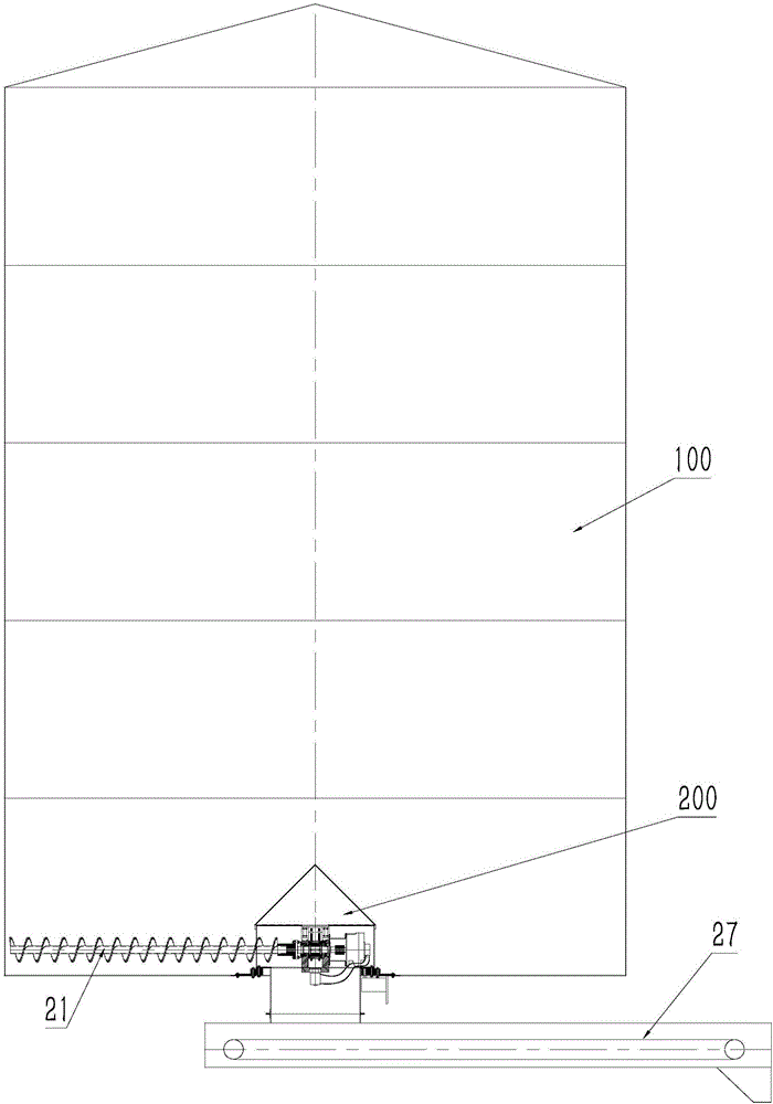
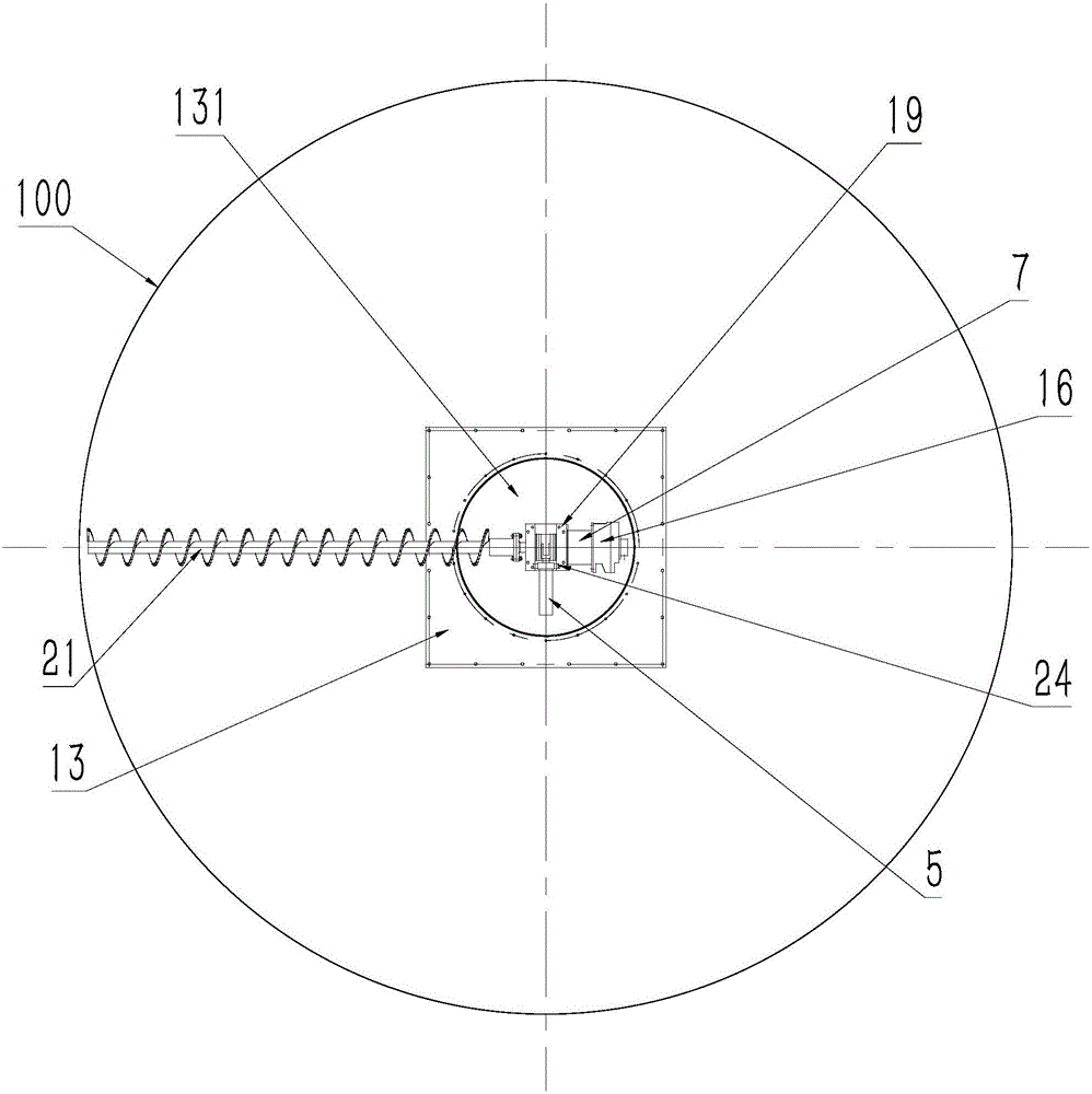
[0026] see figure 1 , 2 In the cylindrical silo 100 shown, a sweeper 200 is installed at the bottom of the silo.

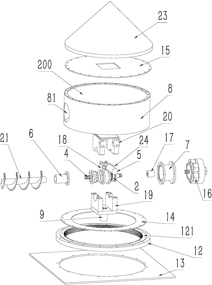
[0027] see Figure 3-5 The sweeper 200 includes a barrel 8, the lower end of the barrel 8 is fixed on the ring gear 121 of the swing support 12 through the swing support flange 14, and the ring gear 121 is rotatably arranged on the outside of the swing support in the circumferential direction. On the support ring 122 , the inner ring gear 121 is fixed in the axial direction relative to the outer support ring 122 . The axes of the cylindrical feed bin 100, the cylinder body 8, and the ring gear 121 are collinear. The outer support ring 122 is fixed on the periphery of the material outlet 131 on the bottom plate 13 .

[0028] A cover plate 15 is fixed on the upper part of the cylinder, and a tapered cover 23 is fixed on the upper part of the cover plate...


PUM


Abstract

The invention provides a bin sweeping machine which can solve the phenomena of bridging and arching of materials in a bin, outputs all the materials in the bin, is small in size and good in effect, and is particularly applicable to output of highly wet materials in the flat-bottom bin. The bin sweeping machine is characterized in that the lower end of a barrel body which has a top and does not have a bottom is rotatably arranged on a bottom plate; a revolution driving device used for driving the barrel body to rotate relative to the bottom plate is arranged on the bottom plate; a bracket is fixed in the barrel body; a screw conveyer penetrates through a material inlet in the side wall of the barrel body and stretches to the outer part of the barrel body in the radial direction of the barrel body; a material outlet which communicates with the bottom of the barrel body is formed in the bottom plate; the screw conveyer is rotatably arranged on the bracket; an autorotation hydraulic motor used for driving the screw conveyer to rotate around the axis relative to the bracket is further arranged on the bracket; the output end of the autorotation hydraulic motor is connected with the screw conveyer; external hydraulic oil is supplied to the autorotation hydraulic motor through a rotation connector; the rotation connector is arranged on the bracket; and a rotating shaft of the rotation connector and the axis of the barrel body are coaxial.

Description

technical field [0001] The technology relates to a sweeping machine and a silo for exporting powdery or granular materials in the silo. Background technique [0002] If the powdery or granular materials in the silo flow out naturally, the speed is slow, and the materials are easy to bridge and arch and cannot flow out, especially for feed with high moisture content, biomass particles, etc., it is easier to bridge and arch. It is difficult to flow out of the warehouse. Contents of the invention [0003] The purpose of the present invention is to provide a sweeping machine capable of destroying the bridging and arching of materials in the silo, exporting all the materials in the silo, and having a small size and good effect. It is especially suitable for cleaning high moisture content materials in flat bottom silos. export. [0004] In the sweeping machine of the present invention, the lower end of a cylinder with a top and bottom is rotatably arranged on the bottom plate,...

Claims


Application Information

Patent Timeline
IPC IPC(8): B65D88/68
CPCB65D88/68
Inventor 蒋贯虹
Owner 溧阳市金诺机械有限公司
Why Eureka
Try Eureka