Tube stock conveying and clamping device

A clamping device and pipe technology, which is applied in the direction of conveyors, conveyor objects, transportation and packaging, etc., can solve the problems of single function, poor coordination, sliding pipes, etc., and achieve good control coordination, high adjustment and clamping efficiency, Ensure the effectiveness of the guiding effect

Inactive Publication Date: 2017-05-31
WUXI MINGZHU TURBOCHARGER MFG
View PDF7 Cites 2 Cited by
  • Summary
  • Abstract
  • Description
  • Claims
  • Application Information

AI Technical Summary

Problems solved by technology

[0002] In the prior art, after the production of the pipes is finished, the processed and formed pipes need to be transported. Before the outward transport, the pipes need to be arranged and transported in translation. When the existing conveying device transports the pipes, when the pipes are not arranged neatly, It is easy to slip, and then may collide, affecting the normal transportation of the pipeline
[0003] The Chinese invention patent with the notification number CN204477497 provides an adjustable pipeline clamping conveying mechanism, which controls the lowering movement of the lifting rod through a synchronous lifting motor to control the level of the sheath, the upper conveyor belt and the lower conveyor belt, and the upper and lower conveyor belts. The horizontal distance between the conveyor belt and the lower conveyor belt is just enough to meet the diameter of the pipe. During the conveying process, the horizontal bar can tightly wrap the pipe. The process is relatively complicated. Obviously, only the upper conveyor belt or the lower conveyor belt can be controlled separately. The adjustment and clamping efficiency is low and the coordination is poor.
[0004] In addition, it can only play a guiding role and has a single function, and it needs to be equipped with a conveying device

Method used


Image

  • Tube stock conveying and clamping device
  • Tube stock conveying and clamping device
  • Tube stock conveying and clamping device

Examples


Embodiment Construction

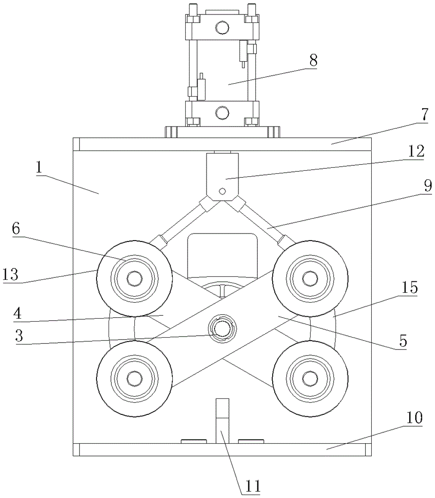
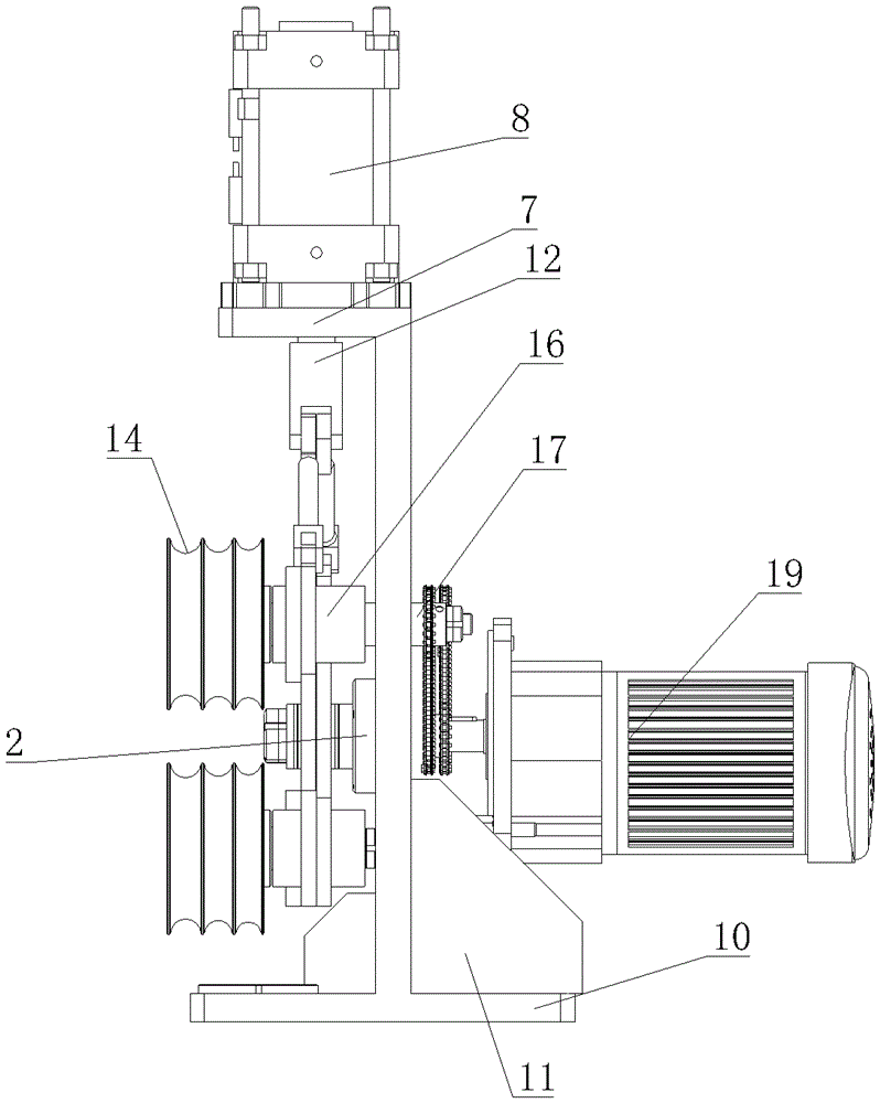
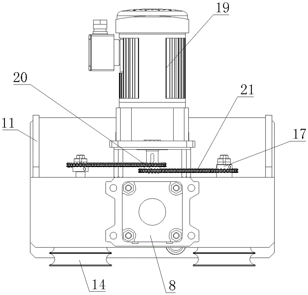
[0016] See figure 1 , figure 2 , image 3 , Figure 4 , a pipe conveying and clamping device, including a frame 1, a bearing seat 2 is arranged on the frame 1, a main shaft 3 is installed on the bearing seat 2, and a first mounting plate 4 and a second mounting plate 5 are respectively rotatably mounted on On the main shaft 3, a shaft hole is provided at the center of the first mounting plate 4 and the second mounting plate 5, and the first mounting plate 4 and the second mounting plate 5 are mounted on the main shaft through the shaft hole and the main shaft 3 respectively. The mounting plate 4 and the second mounting plate 5 are arranged alternately. The two ends of the first mounting plate 4 and the second mounting plate 5 are respectively equipped with a guide wheel device. 4 and the guide wheels 6 at both ends of the second mounting plate 5, the upper end of the frame is provided with a top plate 7, on the top plate 7, a cylinder 8 is installed directly above the corr...


PUM


Abstract

The invention provides a tube stock conveying and clamping device. The tube stock conveying and clamping device can drive a tube stock to be conveyed, can also press the tube stock tightly when conveying the tube stock and is good in control coordination and high in regulating and clamping efficiency. The tube stock conveying and clamping device comprises a rack. The rack is provided with a bearing pedestal, and a main shaft is arranged on the bearing pedestal. A first installation plate and a second installation plate are rotatably arranged on the main shaft and arranged in a staggered manner. Guide wheel devices are arranged at the two ends of the first installation plate and the two ends of the second installation plate. An air cylinder is arranged at the upper end of the rack and arranged over the main shaft. A piston rod of the air cylinder is vertically and downwards arranged and connected with a connecting rod in a hinged manner, and the connecting rod is connected with the upper end of the first installation plate and the upper end of the second installation plate in a hinged manner. Rotating grooves are formed in the rack, rotating shafts which are arranged on guide wheel bearing pedestals and used for driving the guide wheels to rotate backwards extend out to penetrate the corresponding rotating grooves and are provided with driven sprockets, a gear motor is arranged on the rear side of the rack, and a drive sprocket is arranged on the gear motor and connected with the driven sprockets through chains.

Description

technical field [0001] The invention relates to the technical field of pipe conveying devices, in particular to a pipe conveying clamping device. Background technique [0002] In the prior art, after the production of the pipes is finished, the processed and formed pipes need to be transported. Before the outward transport, the pipes need to be arranged and transported in translation. When the existing conveying device transports the pipes, when the pipes are not arranged neatly, It is easy to slip, and then may collide, affecting the normal transportation of the pipeline. [0003] The Chinese invention patent with the notification number CN204477497 provides an adjustable pipeline clamping conveying mechanism, which controls the lowering movement of the lifting rod through a synchronous lifting motor to control the level of the sheath, the upper conveyor belt and the lower conveyor belt, and the upper and lower conveyor belts. The horizontal distance between the conveyor b...

Claims


Application Information

Patent Timeline
Patent Type & Authority Applications(China)
IPC IPC(8): B65G47/24B65G47/26
CPCB65G47/24B65G47/26B65G2201/0217
Inventor 尤梦蝶
Owner WUXI MINGZHU TURBOCHARGER MFG
Why Eureka
Try Eureka