Adjustable pay-off rack

A pay-off stand, adjustable technology, applied in the direction of conveying filamentous materials, thin material processing, transportation and packaging, etc., can solve the problem that the pay-off stand is not suitable for releasing household wires, the mechanical structure of the pay-off stand is complex, the axis Inconsistent hole size and other problems, achieve good social and economic benefits, ensure mechanical strength and electrical conductivity, and smooth wire release

Inactive Publication Date: 2017-05-31
国网河北省电力有限公司宁晋县供电分公司
View PDF10 Cites 3 Cited by
  • Summary
  • Abstract
  • Description
  • Claims
  • Application Information

AI Technical Summary

Problems solved by technology

[0003] The mechanical structures of all kinds of pay-off racks currently on the market are relatively complicated, suitable for large-scale electric power construction, with power equipment devices, which are not easy to move, and the household wires need to be moved frequently, so the current pay-off racks are releasing the household wires. It is very inapplicable when it is used, it will increase the labor intensity of workers
At the same time, corresponding to wires of different specifications, the size of the axis hole is often inconsistent, and the diameter of the threading shaft of the pay-off frame cannot be adjusted, causing the wire to shake radially on the threading shaft of the pay-off frame, and the process of paying off is unstable.

Method used


Image

  • Adjustable pay-off rack
  • Adjustable pay-off rack
  • Adjustable pay-off rack

Examples


Embodiment Construction

[0019] The present invention will be further described in detail below in conjunction with the accompanying drawings and specific embodiments.

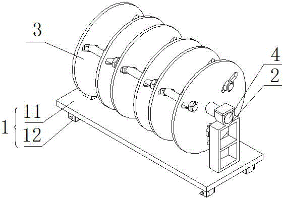
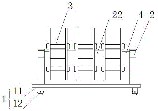
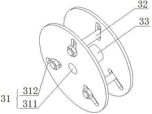
[0020] Such as Figure 1 to Figure 4 As shown, an adjustable pay-off frame includes a base 1, a shaft seat 2, a support shaft 4, and more than one pay-off reel 3 arranged on the support shaft 4, and the pay-off reel 3 includes two belt centers The circular wire reel 31 and the stud 32 of the hole 311, the support shaft 4 passes through the central hole 311, and the circular wire reel 31 is provided with more than 3 long slot holes 312 or more than 3 rows of holes 313, Each row of holes 313 has a plurality of corresponding round holes, and the slotted holes 312 or each row of holes 313 are evenly arranged in the circumferential direction and arranged radially along the circular wire reel 31, and the studs 32 run through the two circular wires. The slotted hole 312 or circular hole corresponding to the disc 31 is locked with nuts at bo...


PUM


Abstract

The invention provides an adjustable pay-off rack, and relates to the technical field of cable construction. The adjustable pay-off rack comprises a base, a shaft base, a supporting shaft and one or more pay-off discs arranged on the supporting shaft. Each pay-off disc comprises two circular wire discs with center holes and studs. The supporting shaft penetrates the center holes. Each circular wire disc is provided with three or more long slotted holes or three or more rows of holes. A plurality of circular holes correspond to each row of holes. The long slotted holes or the holes in each row are evenly distributed in the circumference direction and arranged in the radial direction of the corresponding circular wire disc. The studs penetrate the long slotted holes or the circular holes corresponding to the two circular wire discs, and the two ends of each stud are locked through nuts. The adjustable pay-off rack is easy to operate and is suitable for various specifications of wire rolls with axis holes different in size. An operator can move and use the adjustable pay-off rack conveniently in the operation process, pay-off operation is smooth, damage caused by small circle forming in the pay-off process is avoided, mechanical strength and electric conduction performance of wires are guaranteed, the pay-off operation difficulty is lowered, the work efficiency of the operator is improved, and good social benefits and economic benefits are achieved.

Description

technical field [0001] The invention relates to the technical field of cable construction, in particular to an adjustable pay-off frame. Background technique [0002] When the power supply company is working, it often encounters a process that requires unwinding operations, and a pay-off rack is needed to avoid damage to the wires caused by small circles during the unwinding process, which will affect the mechanical strength and mechanical strength of the wires. Electrical conductivity. At the same time, the pay-off rack can also effectively increase the speed of pay-off, reduce the difficulty of pay-off for operators, and ensure that the wires are not damaged. [0003] The mechanical structures of all kinds of pay-off racks currently on the market are relatively complicated, suitable for large-scale electric power construction, with power equipment devices, which are not easy to move, and the household wires need to be moved frequently, so the current pay-off racks are rel...

Claims


Application Information

Patent Timeline
Patent Type & Authority Applications(China)
IPC IPC(8): B65H49/32
CPCB65H49/32B65H2701/34
Inventor 武晋晓
Owner 国网河北省电力有限公司宁晋县供电分公司
Why Eureka
Try Eureka