Eureka AIR delivers breakthrough ideas for toughest innovation challenges, trusted by R&D personnel around the world.

Lifting translation machine and steel rail lifting translation equipment

A lifting mechanism and machine base technology, applied in the direction of lifting devices, lifting frames, etc., can solve problems such as high labor intensity, and achieve the effect of low labor intensity, large lifting force, stable and reliable operation

Active Publication Date: 2017-05-31
湖南煜欣轨道装备科技工程有限公司
View PDF6 Cites 1 Cited by
  • Summary
  • Abstract
  • Description
  • Claims
  • Application Information

AI Technical Summary

Problems solved by technology

[0009] The purpose of the present invention is to provide a lifting translation machine and rail lifting translation equipment to solve the technical problem of high labor intensity of the user existing in the prior art

Method used


Image

  • Lifting translation machine and steel rail lifting translation equipment
  • Lifting translation machine and steel rail lifting translation equipment
  • Lifting translation machine and steel rail lifting translation equipment

Examples


Embodiment Construction

[0047] The technical solutions of the present invention will be clearly and completely described below in conjunction with the accompanying drawings. Apparently, the described embodiments are part of the embodiments of the present invention, but not all of them. Based on the embodiments of the present invention, all other embodiments obtained by persons of ordinary skill in the art without making creative efforts belong to the protection scope of the present invention.

[0048] In the description of the present invention, it should be noted that the terms "center", "upper", "lower", "left", "right", "vertical", "horizontal", "inner", "outer" etc. The indicated orientation or positional relationship is based on the orientation or positional relationship shown in the drawings, and is only for the convenience of describing the present invention and simplifying the description, rather than indicating or implying that the referred device or element must have a specific orientation, ...


PUM


Abstract

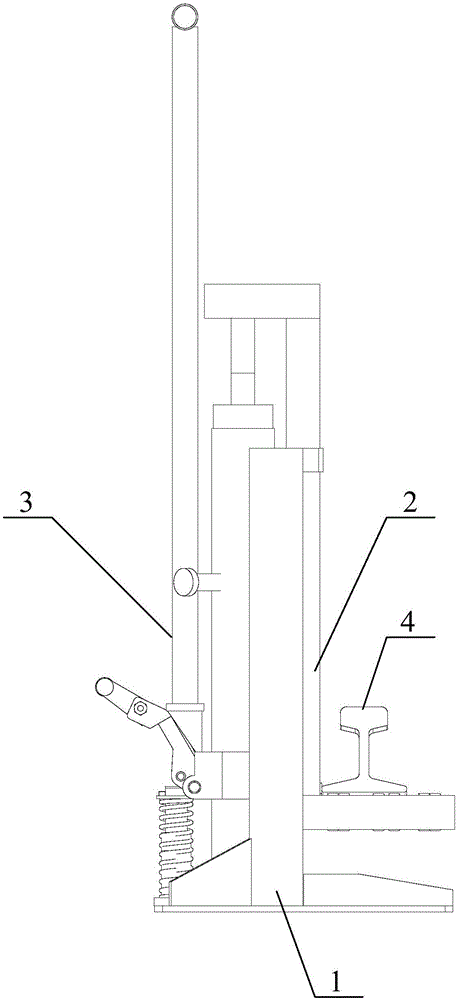
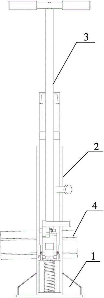
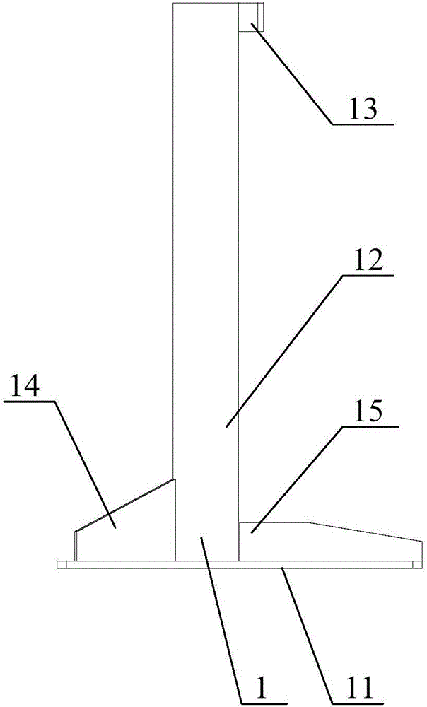
The invention relates to the technical field of steel rail lifting machine, and particularly relates to a lifting translation machine and steel rail lifting translation equipment. The lifting translation machine comprises a hydraulic hoisting mechanism, a crane and a base, wherein the hydraulic hoisting mechanism comprises a hydraulic cylinder and a hydraulic pump; the crane is connected with a piston rod of the hydraulic cylinder, so that the crane is driven by the piston rod to lift or descend. In the lifting translation machine, the hydraulic lifting mechanism is used for supplying a lifting force to the crane and a tool rail, requires labor intensity, and has the advantages of large lifting force, quick action and smooth and reliable operation; I-shaped steel of the base can be used as the guide rail of the crane, so that the crane can be kept to move smoothly and cannot be overturned, rotated or separated when being lifted; a guiding hoop is arranged at the upper part of the base, the crane can move up and down in the guiding hoop, and the crane is prevented from overturned or separated; a rolling bearing is arranged on the lower steel channel of the crane, and the rolling friction is only generated when the tool rail moves, so that the labor intensity of workers can be greatly reduced.

Description

technical field [0001] The invention relates to the technical field of rail lifting machinery, in particular to a lifting translation machine and rail lifting translation equipment. Background technique [0002] In high-speed rail, railway, and highway construction sites, a large number of heavy-duty steel rails are used as tool rails and walking rails. Tool rails are frequently laid and moved, and the workload and labor intensity are very large. A single tool rail weighs 750 kilograms, requiring 16 strong workers to lift, move and align, which is time-consuming and labor-intensive. [0003] At present, at the construction site of railways and highways, a kind of hand-operated rack and pinion rail hoist is widely used. This rack and pinion rail hoist is to rotate the handle by manpower, and the gear with the coaxial deceleration of the handle shaft drives the rack to move up and down to lift and lower the tool rail. But this machine has the following defects: [0004] 1. ...

Claims


Application Information

Patent Timeline
IPC IPC(8): B66F7/18B66F7/28B66F3/42
CPCB66F3/42B66F7/18B66F7/28
Inventor 何颖华李圣金
Owner 湖南煜欣轨道装备科技工程有限公司
Why Eureka
Eureka Blog
Learn More