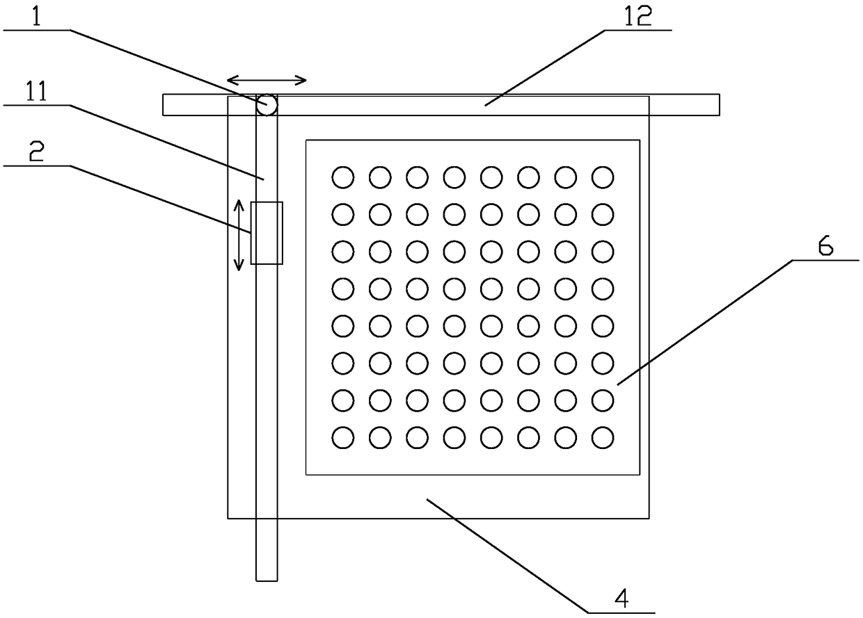
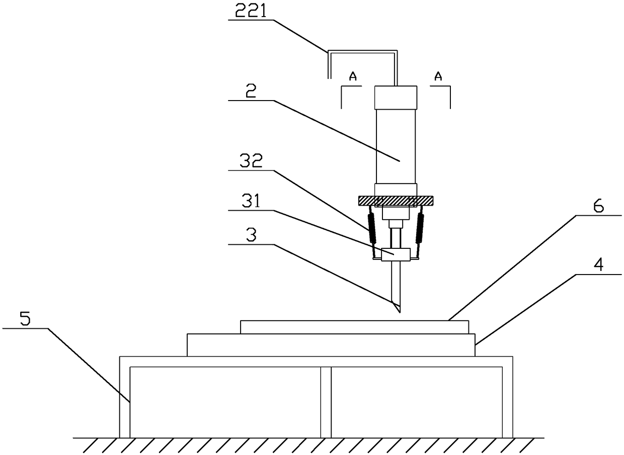
A needle plate knocking device
A needle board and thimble technology, which is applied to needle punching machines, textiles and papermaking, non-woven fabrics, etc., can solve the problems of unsolved steel needles, high labor intensity and low efficiency, and achieve simple structure, low labor intensity and high efficiency. high effect
- Summary
- Abstract
- Description
- Claims
- Application Information
AI Technical Summary
Problems solved by technology
Method used
Image
Examples
Embodiment 1
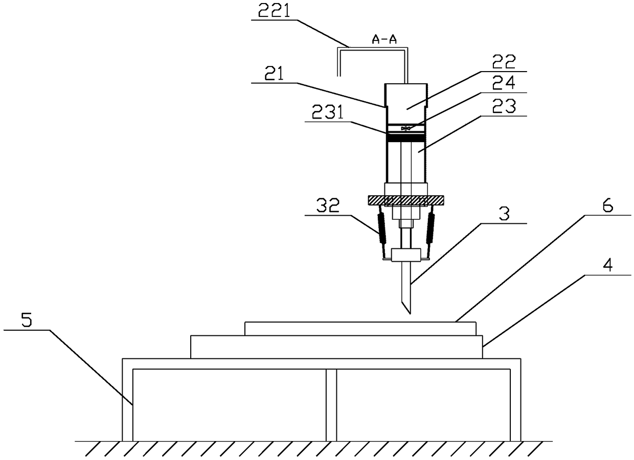
[0043] Such as Figure 2-3As shown, the action mechanism 2 includes an air pressure chamber 22 and a piston chamber 23 arranged in the housing 21, the air pressure chamber 22 and the piston chamber 23 are isolated from each other, and the air pressure chamber 22 and the piston chamber 23 Connected by a pipeline, the pipeline is provided with a differential pressure valve 24; the piston chamber 23 is provided with a piston 231, and a metal baffle is fixed on the lower surface of the piston, and the metal baffle is fixed to the thimble 3 Connection; the upper part of the air chamber 22 is provided with an inflatable pipeline 221, and the inflatable pipeline 221 communicates with the inflatable bag. Inflate the air chamber by pinching the inflatable bag manually or using other methods. When the pressure in the air chamber is greater than the critical value of the differential pressure valve, the differential pressure valve opens, and the gas instantly rushes into the piston chamb...
Embodiment 2
[0045] Such as Figure 4-5 As shown, the actuating mechanism includes a counterweight disposed in the housing 21 and a tension spring 26 disposed between the counterweight 25 and the housing, the counterweight 25 is provided with a handle 251, so The handle 251 extends out of the housing 21 . Use the spring to manually store energy, and then use the kinetic energy when the spring returns to hit the thimble to complete the knocking action. When in use, first pull the handle to store energy in the spring. While pulling the handle, adjust the action mechanism to the area that needs to be struck, and then release the handle to complete the strike. The kinetic energy generated by the spring reset is released instantly to achieve the purpose of strike. Simple and convenient, one person can complete the operation, easy to use and high efficiency.
[0046] In order to further facilitate the operation and increase the spring tension at the same time, the bottom of the counterweight 2...
Embodiment 3
[0050] Such as Figure 6-7 As shown, the actuating mechanism includes a limit block 27 arranged at the top of the thimble 3 , the limit block 27 is provided with a tension spring 271 , and one end of the tension spring 271 is fixed on the limit block 27 , the other end of the tension spring 271 is fixed on the inner wall of the casing 21; the top of the casing 21 is provided with a hand wheel 28, and the hand wheel 28 is connected to an eccentric wheel 281 through a drive shaft, and the eccentric wheel 281 A transmission shaft 282 is provided on it, one end of the transmission shaft 282 is movably connected to the eccentric wheel 281 , and the other end of the transmission shaft 282 is fixedly connected with the limit block 27 .
[0051] Compared with the second embodiment, the setting of the hand wheel makes the force required for the spring to store energy small, reducing the labor intensity. Controlled by hand wheel, quick release and fast energy storage to improve product...
PUM
 Abstract
Description
Claims
Application Information
 - R&D
- Intellectual Property
- Life Sciences
- Materials
- Tech Scout
- Unparalleled Data Quality
- Higher Quality Content
- 60% Fewer Hallucinations
Browse by: Latest US Patents, China's latest patents, Technical Efficacy Thesaurus, Application Domain, Technology Topic, Popular Technical Reports.
© 2025 PatSnap. All rights reserved.Legal|Privacy policy|Modern Slavery Act Transparency Statement|Sitemap|About US| Contact US: help@patsnap.com


