
An adjustable road roller mud scraper

A mud scraper and road roller technology, which is applied in the field of adjustable road roller mud scrapers, can solve the problems of difficult removal of mud scraper sludge, time-consuming adjustment of mud scrapers, and reduced mud scraping efficiency, so as to improve mud scraping efficiency, Reduce labor intensity and ensure cleaning effect

Inactive Publication Date: 2019-09-10
王江丽
View PDF4 Cites 1 Cited by
  • Summary
  • Abstract
  • Description
  • Claims
  • Application Information

AI Technical Summary

Problems solved by technology

[0003] At present, after the mud scraper sticks to the steel wheel, it is fixed with bolts, hangs up and sticks to the steel wheel soil, so that the road surface pressed out is smooth. This method of installing the mud scraper has the following disadvantages: 1. There is a gap between the mud scraper and the steel wheel. Fast friction creates a gap that affects the mud scraping effect, resulting in a greatly reduced mud scraping efficiency; 2. When the roller turns, the position of the steel wheel changes, causing the mud scraper to move or deform; 3. The adjustment of the mud scraper is time-consuming
As a result, mud scrapers are rarely used now, and many people use wire ropes to scrape off the mud on the steel wheels; 4. The residual sludge on the scraper is not easy to remove, so an adjustable road roller scraper is urgently needed to solve the above problems. problems

Method used


Image

  • An adjustable road roller mud scraper
  • An adjustable road roller mud scraper
  • An adjustable road roller mud scraper

Examples


Embodiment Construction

[0018] In order to make the technical means, creative features, goals and effects achieved by the present invention easy to understand, the present invention will be further described below in conjunction with specific embodiments.

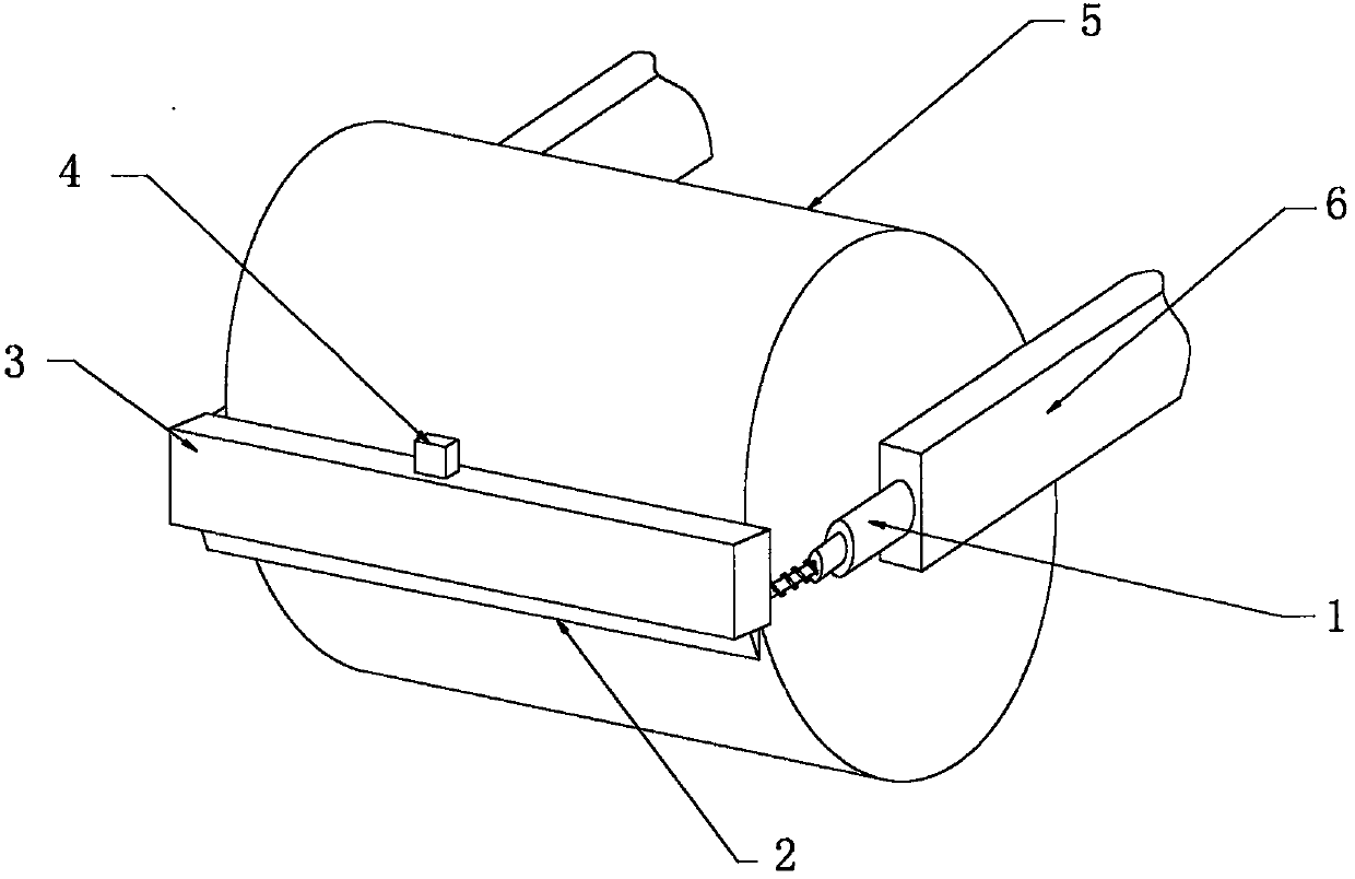
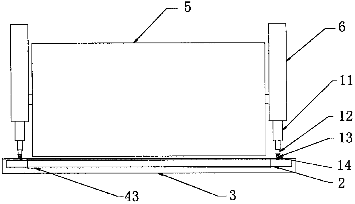
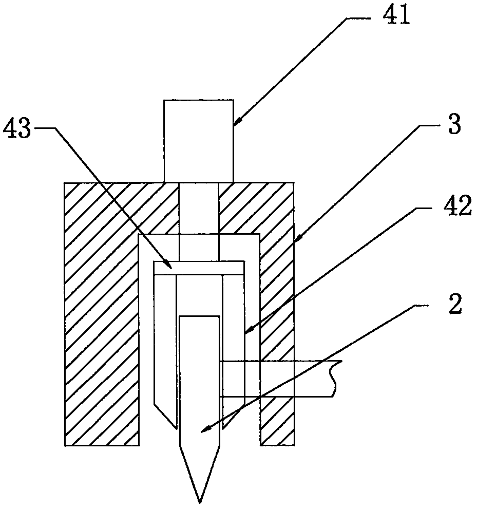
[0019] see Figure 1-Figure 3 , the present invention provides a technical solution: an adjustable road roller mud scraper, including a main structure, a mud scraping adjustment mechanism 1 and a mud removal mechanism 4, characterized in that the main structure is composed of a steel wheel 5, a supporting beam 6, a protective The cover 3 and the mud scraper 2 are composed of two sets of supporting beams 6, the steel wheel 5 is installed between the two sets of supporting beams 6, the protective cover 3 is assembled in the middle of the front end of the steel wheel 5, and the protective cover 3 passes through the connecting plate Connected with two sets of supporting beams 6 , the mud scraper 2 is arranged in the protective cover 3 .

[0020] The ...


PUM


Abstract

The invention provides an adjustable type road roller mud scraper. The adjustable type road roller mud scraper comprises support transverse beams, a steel wheel, a protective cover, a mud scraper body, hydraulic cylinders, guide sleeves, guide rods, return springs, an electric cylinder, scraping knives and a connecting base, wherein the hydraulic cylinder is arranged in the middle part of front end surface of each support transverse beam; each guide sleeve is assembled at the front end surface of the corresponding hydraulic cylinder; the back end of each guide rod is arranged in the corresponding guide sleeve, and the front end of each guide rod penetrates through the protective cover and is connected with the mud scraper body; each return spring is coated at the outer surface of the corresponding guide rod, the front end of each return spring is connected with the mud scraper body, and the back end of each return spring is connected with the corresponding guide sleeve; the electric cylinder is arranged in the middle part of the upper end surface of the protective cover; the connecting base is arranged in the protective cover; the upper end of the connecting base is connected with the electric cylinder; the upper ends of the two groups of scraping knives are fixedly arranged on the connecting base, and are symmetrically arranged at the front and back sides of the mud scraper body. The adjustable type road roller mud scraper has the advantages that the structure is reasonable, the mud scraping efficiency is improved, the adjusting is convenient, the stability is good, and the reliability is high.

Description

technical field [0001] The invention is an adjustable road roller mud scraper, which belongs to the field of road roller accessory equipment. Background technique [0002] Road rollers, also known as soil compactors, belong to the category of road equipment in construction machinery. They are widely used in the filling and compaction operations of large-scale engineering projects such as high-grade highways, railways, airport runways, dams, and stadiums. They can roll sand , semi-cohesive and cohesive soil, roadbed stabilized soil and asphalt concrete pavement layer, the mud scraper on the road roller is specially designed for removing asphalt pavement, mud and other sundries adhered to the compaction wheel of the road roller during the compaction process of. [0003] At present, after the mud scraper sticks to the steel wheel, it is fixed with bolts, hangs up and sticks to the steel wheel soil, so that the road surface pressed out is smooth. This method of installing the m...

Claims


Application Information

Patent Timeline
Patent Type & Authority Patents(China)
IPC IPC(8): E01C19/23
Inventor 王辉王江丽王永胜
Owner 王江丽
Learn More