
Full-submersible separation type fan foundation

A fan base and separate technology, applied in the direction of basic structure engineering, construction, etc., can solve the problems of large and uneconomical base structure, deep draft of underwater structure, high installation cost, etc., to meet the stability of the fan, reduce the dynamic response, Effect of small wave load

Active Publication Date: 2017-05-31
SOUTHEAST UNIV
View PDF6 Cites 11 Cited by
  • Summary
  • Abstract
  • Description
  • Claims
  • Application Information

AI Technical Summary

Problems solved by technology

Wind energy has not been developed and utilized in sea areas above 30 meters deep
Advantages: small waterline area is less affected by wave loads; Disadvantages: underwater structure has a deep draft, a lot of consumables, and is uneconomical. At the same time, the stiffness of the catenary line is not enough for rolling, pitching, and swaying. This structure is not suitable for within 100 meters Development of Wind Energy in Water Areas
Advantages: This form of foundation has a large water surface area, large restoring moment, and good stability; Disadvantages: The large-scale buoy structure is subjected to large wave loads, and the volume of the foundation structure is huge and uneconomical
Advantages: The tension leg floating foundation has good heave and sway characteristics; Disadvantages: The tension leg structure is complicated, expensive, and installation cost is high
[0007] At present, many floating foundations have been applied to wind power generation all over the world, but due to technical limitations, high cost, and complex loading of floating foundations, they have not been vigorously promoted like fixed foundations in shallow seas.

Method used


Image

  • Full-submersible separation type fan foundation
  • Full-submersible separation type fan foundation
  • Full-submersible separation type fan foundation

Examples


Embodiment Construction

[0036] The present invention will be further described below in conjunction with the accompanying drawings.

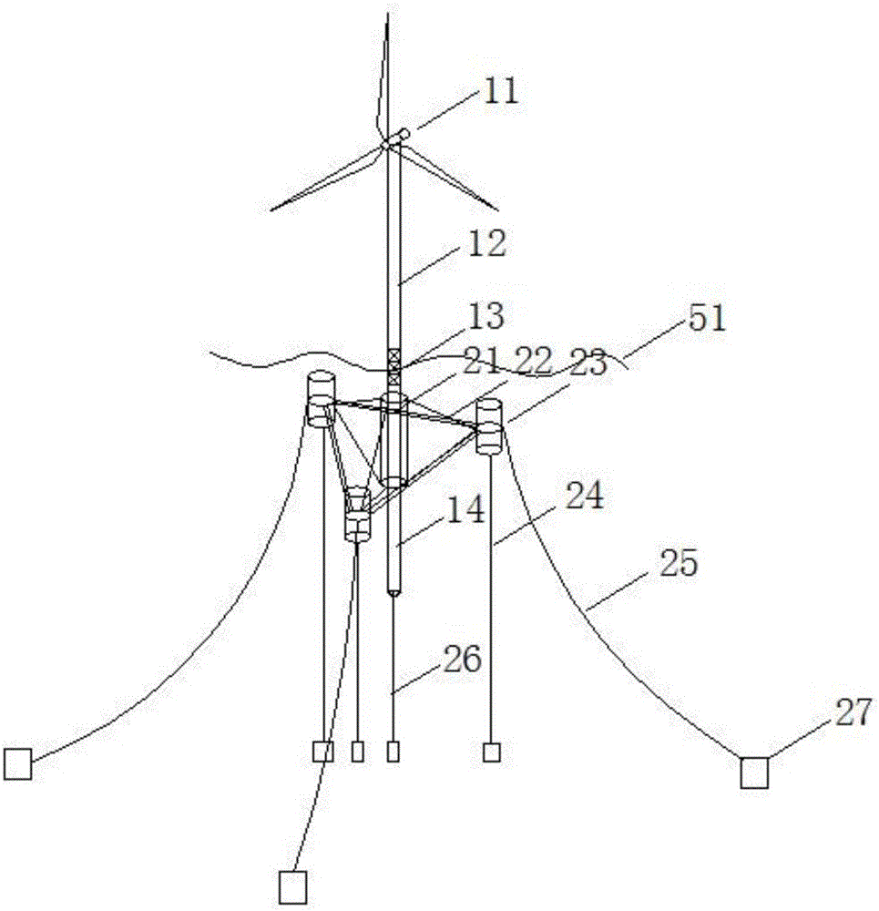
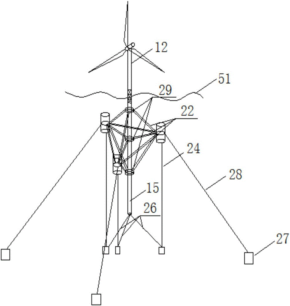
[0037] figure 1 , a fully submerged separated fan foundation, including a fan 11, an upper tower 12, a middle truss 13, a lower buoy structure 14, a middle sleeve 21, a support frame 22, a submerged buoy 23, a first tension line 26, a second Tension line 24, catenary line 25 and suction caisson foundation 27.

[0038] Specifically, the fan 11 is connected to the top of the upper tower 12, the bottom of the upper tower 12 is connected to the top of the middle truss 13, the middle truss is arranged at the sea surface 51, a part of the middle truss is arranged Below the sea surface, the middle truss 13 is a hollow structure, which greatly reduces the impact of sea level waves on the wind turbine. The bottom of the middle truss 13 is connected to the top of the lower buoy structure 14, the buoyancy of the lower buoy structure can be balanced with the self-weight of the f...


PUM


Abstract

The invention discloses a full-submersible separation type fan foundation and relates to the technical field of offshore wind power generation. Through the full-submersible separation type fan foundation, influence on a buoy by wave load is directly avoided, and the whole power response of a fan is obviously lowered. The full-submersible separation type fan foundation mainly comprises two parts including a submerging and surfacing type foundation and a fan system. The submerging and surfacing type foundation is composed of a sleeve, a supporting frame, submerging and surfacing drums, tensioning wires and catenaries; the fan system is composed of a fan and a tower drum; the tower drum penetrates through a middle sleeve, capable of realizing floating up and down; the sleeve is fixedly connected with a submerging and surfacing box through the supporting frame; the sleeve, the supporting frame and the submerging and surfacing drums are fixed beneath the ocean surface to form the submerging and surfacing type foundation, serving as a directed supporting seat of the tower drum, through the tensioning wires and the catenaries; and the bottom of the tower drum is connected with a seabed through the tensioning wires. The full-submersible separation type fan foundation is in a completely-new offshore fan foundation structure form and is suitable for building an offshore fan foundation.

Description

technical field [0001] The invention relates to the technical field of offshore wind power generation, in particular to a submersible-floating wind turbine foundation. Background technique [0002] So far, research on floating wind turbines in my country is still in its infancy. The development of offshore wind farms is currently mostly located in shallow seas with a water depth of 0-30 meters, within 20km from the coast, such as Xiangshui Wind Farm, Donghai Bridge Wind Farm, etc., all adopt fixed support foundations. According to the latest offshore wind resource survey results of the China Meteorological Administration, the installed capacity of wind power in my country's offshore areas within the 5m to 25m water depth line and 50m above sea level is about 200 million kW, and the transitional area within 25m to 50m, sea level The installed capacity of more than 70m above is about 500 million kW, and the wind energy resources in the deep sea area above 100m are more abundan...

Claims


Application Information

Patent Timeline
IPC IPC(8): E02D27/44E02D27/52
CPCE02D27/44E02D27/52
Inventor 戴国亮朱文波龚维明
Owner SOUTHEAST UNIV
Learn More