A steel tube concrete column-u-shaped steel plate composite beam frame

A technology of steel pipe concrete columns and composite beams, which is applied in the direction of girders, joists, and truss beams, etc., can solve the problems that the anchoring steel bars cannot meet the anchorage length requirements, weaken the bearing capacity of components, and reduce the shear bearing capacity, etc., and achieve improved shear resistance Bearing capacity, elimination of section weakening, effect of strengthening connection

Active Publication Date: 2019-06-21
GUANGXI UNIV
View PDF8 Cites 0 Cited by
  • Summary
  • Abstract
  • Description
  • Claims
  • Application Information

AI Technical Summary

Problems solved by technology

Whether the structure of the frame joints is reasonable or not is the key issue that affects the stress of the structure and the difficulty of construction. From the perspective of actual engineering, there are still many problems, such as the frame joints of steel tube concrete and steel concrete composite beams. First, the concrete at the joints is discontinuous, and the beam There is a steel pipe wall between the concrete and the column concrete, which will reduce the shear bearing capacity
The second is that most of the section steel is connected to the outside of the rigid pipe wall, and it is necessary to add a partition inside the steel pipe, or set a ring stiffener outside the pipe, and the structure of the joint is very complicated.
The third is that the horizontal steel bars in the beam members need to pass through the steel pipe wall and be anchored in the concrete in the column, and holes need to be opened on the steel pipe wall, and the anchoring steel bars basically cannot meet the anchorage length requirements specified in the code
For stiffened concrete frames, there is also the problem of complex joint construction. When the longitudinal reinforcement of the beam is anchored in the column, it often needs to pass through the section provided with section steel. The section steel with the column needs to be opened, and the opening will weaken the bearing capacity of the component. , Article 9.1.4 of "Technical Regulations for Steel Concrete Composite Structures" (JGJ138-2001) stipulates that the design should reduce the number of longitudinal steel bars passing through the steel columns in the columns, and should not pass through the steel flanges, and should not be connected with the columns. For the direct welding connection of the inner section steel, when it is necessary to reserve a through hole on the inner section steel web of the column, the section loss rate of the section steel web should be less than 25% of the web area; when it is necessary to reserve a through hole on the inner section steel flange of the column, The bearing capacity of the reserved hole section should be checked and calculated according to the most unfavorable combination of M and N at the column end

Method used


Image

  • A steel tube concrete column-u-shaped steel plate composite beam frame
  • A steel tube concrete column-u-shaped steel plate composite beam frame
  • A steel tube concrete column-u-shaped steel plate composite beam frame

Examples


Embodiment Construction

[0025] The specific embodiments of the present invention will be described in detail below with reference to the accompanying drawings, but it should be understood that the protection scope of the present invention is not limited by the specific embodiments.

[0026] Unless expressly stated otherwise, throughout the specification and claims, the term "comprising" or its conjugations such as "comprising" or "comprising" and the like will be understood to include the stated elements or components, and Other elements or other components are not excluded.

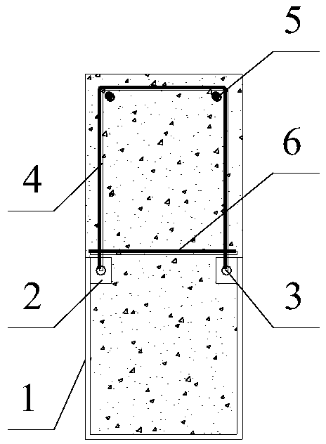
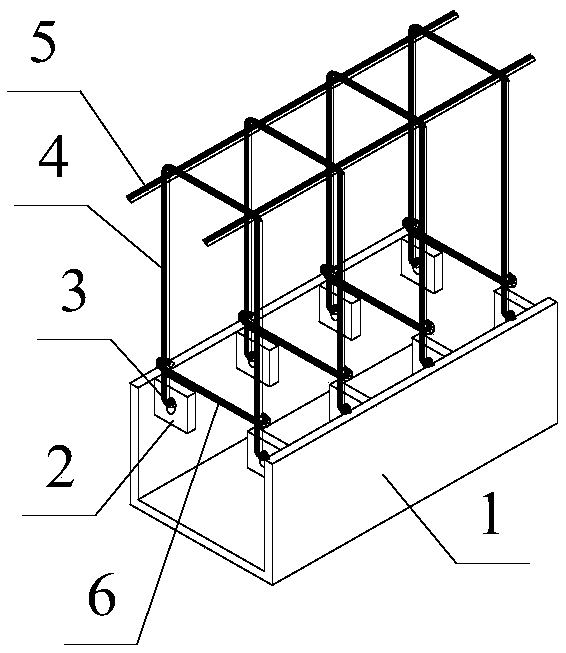
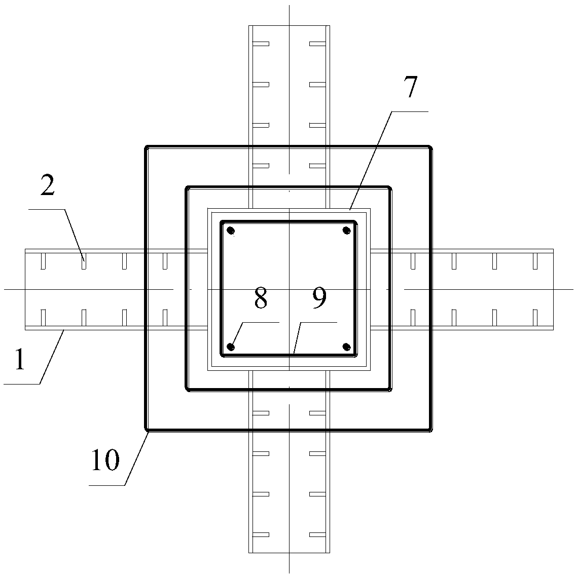
[0027] Figure 1 to Figure 4 A schematic structural diagram of the CFST column-U-shaped steel plate composite beam frame according to the preferred embodiment of the present invention is shown.

[0028] like Figure 1 to Figure 4 As shown, the CFST column-U-shaped steel plate composite beam frame includes: a hollow steel pipe 7, a U-shaped steel plate 1, a connector 2, an open steel frame, a steel cage, a horizontal tie 6 and...


PUM


Abstract

The invention discloses a concrete-filled steel tube column-U-shaped steel plate combined beam frame. The concrete-filled steel tube column-U-shaped steel plate combined beam frame comprises a hollow steel pipe, a plurality of U-shaped steel plates, connecting components, a plurality of open steel bar skeletons and a steel reinforcement cage, wherein the hollow steel pipe is circumferentially and uniformly provided with a plurality of steel pipe wall holes; one end of each U-shaped steel plate is fixed to the corresponding steel pipe wall hole, and the other end of each U-shaped steel plate outwards extends relative to the corresponding steel pipe wall hole; the multiple sets of symmetrical connecting components are all arranged on the inner walls of the U-shaped steel plates; the two open ends of each open steel bar skeleton are separately arranged on the corresponding connecting component; and the steel reinforcement cage is sleeved with the hollow steel pipe. The concrete-filled steel tube column-U-shaped steel plate combined beam frame has the advantages of being simple in joint structure, definite in stress, convenient to construct and the like.

Description

technical field [0001] The invention relates to the technical field of steel and concrete composite frames, in particular to a steel tube concrete column-U-shaped steel plate composite beam frame. Background technique [0002] Steel and concrete composite structure is a common structural form in modern building structures. Because it can give full play to the mechanical advantages of the two materials, it is widely used in large-span structures and high-rise buildings. It also has good ductility, which expands its range of applications. Commonly used composite columns in engineering include concrete-filled steel tubular columns, stiff concrete columns, and composite beams include profiled steel-concrete composite beams and stiff concrete beams, which are combined in pairs to form different types of composite frames. Among them, the most widely used are concrete-filled steel tube-steel-concrete composite beam frame, concrete-filled steel tube column-stiffened beam frame, and...

Claims


Application Information

Patent Timeline
Patent Type & Authority Patents(China)
IPC IPC(8): E04B1/19E04C3/29
CPCE04B1/1903E04B2001/1936E04C3/293
Inventor 周理苏益声
Owner GUANGXI UNIV
Why Eureka
Try Eureka