
Hydraulic oscillator

A technology of hydraulic oscillator and power sub-section, which is applied to vibration drilling, vibration generating devices, wellbore/well components, etc. effect, the effect of reducing friction

Active Publication Date: 2017-05-31
临沂高新自来水有限公司
View PDF6 Cites 17 Cited by
  • Summary
  • Abstract
  • Description
  • Claims
  • Application Information

AI Technical Summary

Problems solved by technology

[0003] At present, the corresponding tools developed at home and abroad include: impactors, vertical drilling tools, rotary steering tools, hydraulic pressurizers, drag reduction tools and jars, etc. These tools reduce friction to a certain extent, but these tools The functions are relatively single, the technical performance and quality are still at a low level, and there are the following defects: one is limited by the structure, the vibration mode is single, the oscillation effect is not good, and the friction cannot be fundamentally reduced.
The second is that the impact parameters are unreasonable. Higher impact force and oscillation frequency are required to meet drilling needs, so more expensive and higher-performance drilling tools and drill bits must be configured.
The third is that the service life is short and the continuous working ability is poor, thereby increasing the number of trips and seriously affecting the ROP

Method used


Image

  • Hydraulic oscillator
  • Hydraulic oscillator
  • Hydraulic oscillator

Examples


Embodiment Construction

[0024] The present invention will be further described below in conjunction with the accompanying drawings. The following examples are only used to illustrate the technical solution of the present invention more clearly, but not to limit the protection scope of the present invention.

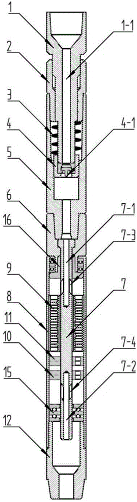
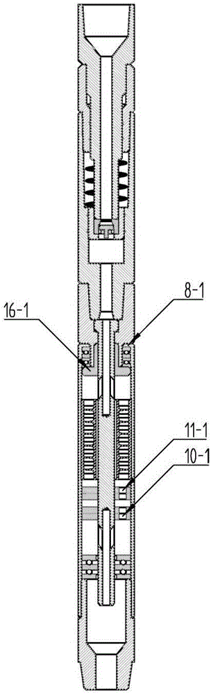
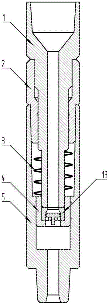
[0025] Such as Figures 1 to 6 As shown, a hydraulic oscillator includes: a vibrating short joint and a dynamic short joint connected with the vibrating short joint.

[0026] The vibrating joint includes: sliding shaft 1, sliding sleeve 2, vibrating spring 3, piston terminal 4 and vibrating housing 5. The sliding shaft 1 has a flow channel I1-1 extending along its axial direction, the upper end of the sliding shaft 1 is connected with the drill pipe, and the sliding shaft 1 and the sliding sleeve 2 form a sliding connection along the axial direction through splines. The sliding sleeve 2 is connected with the vibrating housing 5 . A piston terminal 4 is installed at the lower end of the slidin...


PUM


Abstract

The invention discloses a hydraulic oscillator. The hydraulic oscillator comprises a vibration short section and a dynamic short section connected with the vibration section; the vibration short section comprises a slide shaft, a slide sleeve, a vibration spring, a piston terminal and a vibration shell; the upper end of the slide shaft is connected to a drill rod, and the slide shaft and the slide sleeve are in slide connection in the axial direction of a spline through the spline; the slide sleeve is connected with the vibration shell; a vibration spring is installed between the lower end of the slide sleeve and the vibration shell; the lower end of the slide shaft is provided with the piston terminal; the dynamic short section comprises a connection sleeve, a mandrel, a rotation shell, turbine blades, a fixed valve and an eccentric movable valve; the lower end of the connecting sleeve and the upper end of the rotation shell form one-way rotation connection in the axial directions of the lower end of the connecting sleeve and the upper end of the rotation shell; the upper end of the mandrel is connected with the connecting sleeve, and the lower end of the mandrel is arranged in the rotation shell; the inner wall is provided with the turbine blades and the eccentric movable valve in sequence from top to bottom; the mandrel is provided with the fixed valve. The hydraulic oscillator has the advantages that vibration and superposition effects can be compounded, and thus the friction force in the drilling process is drastically reduced.

Description

technical field [0001] The invention belongs to the technical field of oil exploitation equipment, and in particular relates to a hydraulic oscillator. Background technique [0002] With the development of the petroleum industry, the current oil field drilling has gradually developed from the original directional well to the horizontal well, and in the process of horizontal well drilling, due to the gravity of the drilling tool itself, the friction between the drilling tool and the well wall during drilling If it is too large, it will seriously affect the drilling speed, and even cause the backing pressure of the drilling tool to fail to pressurize the drill bit. Therefore, reducing friction, reducing stuck pipe accidents, increasing dynamic bit pressure, and improving drilling efficiency are problems that need to be solved urgently in current drilling projects. The study found that when the mud passes through the drilling tool, the mud pressure can change periodically, so ...

Claims


Application Information

Patent Timeline
IPC IPC(8): E21B7/24E21B28/00
CPCE21B7/24E21B28/00
Inventor 姜进涛
Owner 临沂高新自来水有限公司
Features
  • Generate Ideas
  • Intellectual Property
  • Life Sciences
  • Materials
  • Tech Scout
  • Unparalleled Data Quality
  • Higher Quality Content
  • 60% Fewer Hallucinations
Learn More