Eureka AIR delivers breakthrough ideas for toughest innovation challenges, trusted by R&D personnel around the world.

Automatic drainage control system

A control system and automatic drainage technology, applied in drainage, pump control, machine/engine, etc., can solve the problems of motor idling and burning motor, drainage system automation degree is not high, etc.

Active Publication Date: 2017-05-31
HUAINAN MINING IND GRP
View PDF7 Cites 2 Cited by
  • Summary
  • Abstract
  • Description
  • Claims
  • Application Information

AI Technical Summary

Problems solved by technology

[0003] The technical problem to be solved by this invention is that the degree of automation of the drainage system is not high, and special personnel are required to take care of it, and it may also cause the motor to burn in idling. Therefore, an automatic drainage system is provided here.

Method used


Image

  • Automatic drainage control system
  • Automatic drainage control system

Examples


Embodiment Construction

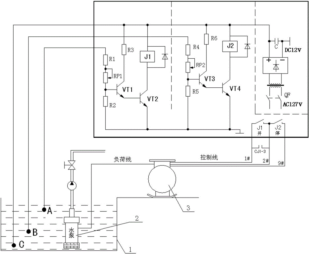
[0024] Such as figure 1 As shown, an automatic drainage control system includes a magnetic starter, a power module, an electrode sensor, a relay J1, a relay J2, a first control loop, and a second control loop. The magnetic starter 3 is a switch for controlling the water pump 2, and the relay The normally open contact of J1 and the normally open contact of the relay J2 are connected in series and respectively in parallel on the three pins of the magnetic starter 3 .

[0025] The two ends of the coil of the relay J1 and the coil of the relay J2 are respectively connected with anti-reverse diodes in parallel, and the output terminals of the anti-reverse diodes are connected with the output terminals of the power supply.

[0026] The electrode sensor includes a lower limit water level sensor, an upper limit water level sensor and a third water level sensor. The horizontal heights of the third water level sensor, the lower limit water level sensor and the upper limit water level s...


PUM


Abstract

The invention provides an automatic drainage control system. The automatic drainage control system comprises a magnetic starter, a power module, an electrode sensor, a relay J1, a relay J2, a first control loop and a second control loop. The magnetic starter controls the on-off state of a water pump, the normally open contact of the relay J1 is connected with the normally open contact of the relay J2 in series, and the normally open contact of the relay J1 and the normally open contact of the relay J2 are separately connected with three pins of the magnetic starter in parallel. The electrode sensor comprises a lower limit water level sensor body and an upper limit water level sensor body. The first control loop comprises a first input end, a second input end and an output end. The first input end is connected with the upper limit water level sensor body, the second input end is connected with the output end of the power module, and a coil of the relay J1 is arranged between the output end of the first control loop and a power end. The first control loop is identical with the second control loop. The system has the advantages of being capable of achieving automatic drainage and effectively preventing the situation that a water pump idles due to insufficient water.

Description

technical field [0001] The invention relates to the field of automatic drainage, in particular to an automatic drainage control system. Background technique [0002] The drainage system plays a very important role in ensuring the normal production of the mine. At present, the drainage method of many mines is: the water in each excavation and belt conveyor roadway flows to the pool 1 in the low-lying part of the roadway through the ditch of the branch roadway, and is discharged to the ditch of the horizontal main road by various water pumps, and flows through the ditch of the horizontal main road by itself To the central water tank, and then directly discharged to the ground by the central water pump. In this process, the traditional manual care of the water pump is still used to drain the water, which increases the labor intensity, is labor-intensive and time-consuming, and the reliability of the equipment operation is low, often causing dry pumps without water, and the phe...

Claims


Application Information

Patent Timeline
IPC IPC(8): E21F16/00F04B49/06
CPCE21F16/00F04B49/06
Inventor 李明王利赵伟徐德生邬浩军王亮王国庆刘明王来浩
Owner HUAINAN MINING IND GRP
Why Eureka
Eureka Blog
Learn More