Lubricating system for a rotary engine

A rotor engine and lubrication system technology, applied in the direction of engine lubrication, engine speed, engine components, etc., can solve the problems of seal friction and wear, seal failure, lubrication difficulties, etc., to ensure lubrication, ensure reliable sealing, and prolong service life The effect of longevity

Active Publication Date: 2019-01-01
BEIJING INSTITUTE OF TECHNOLOGYGY
View PDF6 Cites 0 Cited by
  • Summary
  • Abstract
  • Description
  • Claims
  • Application Information

AI Technical Summary

Problems solved by technology

[0004] Aiming at the difficulties of radial oil supply and lubrication of small rotor engines, serious friction and wear of sealing plates, and easy failure of seals, the technical problem to be solved in the lubrication system for rotor engines disclosed by the present invention is to provide a kind of lubrication system with reasonable structure and reliable operation. The radial seal oil supply mechanism of the rotor engine realizes reliable and effective oil supply during operation through the control unit, respectively guarantees the lubrication of the eccentric shaft-bearing, seal plate-cylinder body, thereby reducing friction and wear, ensuring reliable sealing, and extending the length of the eccentric shaft, Longer service life of bearings, seals and cylinders, improving rotary engine performance

Method used


Image

  • Lubricating system for a rotary engine
  • Lubricating system for a rotary engine
  • Lubricating system for a rotary engine

Examples


Embodiment 1

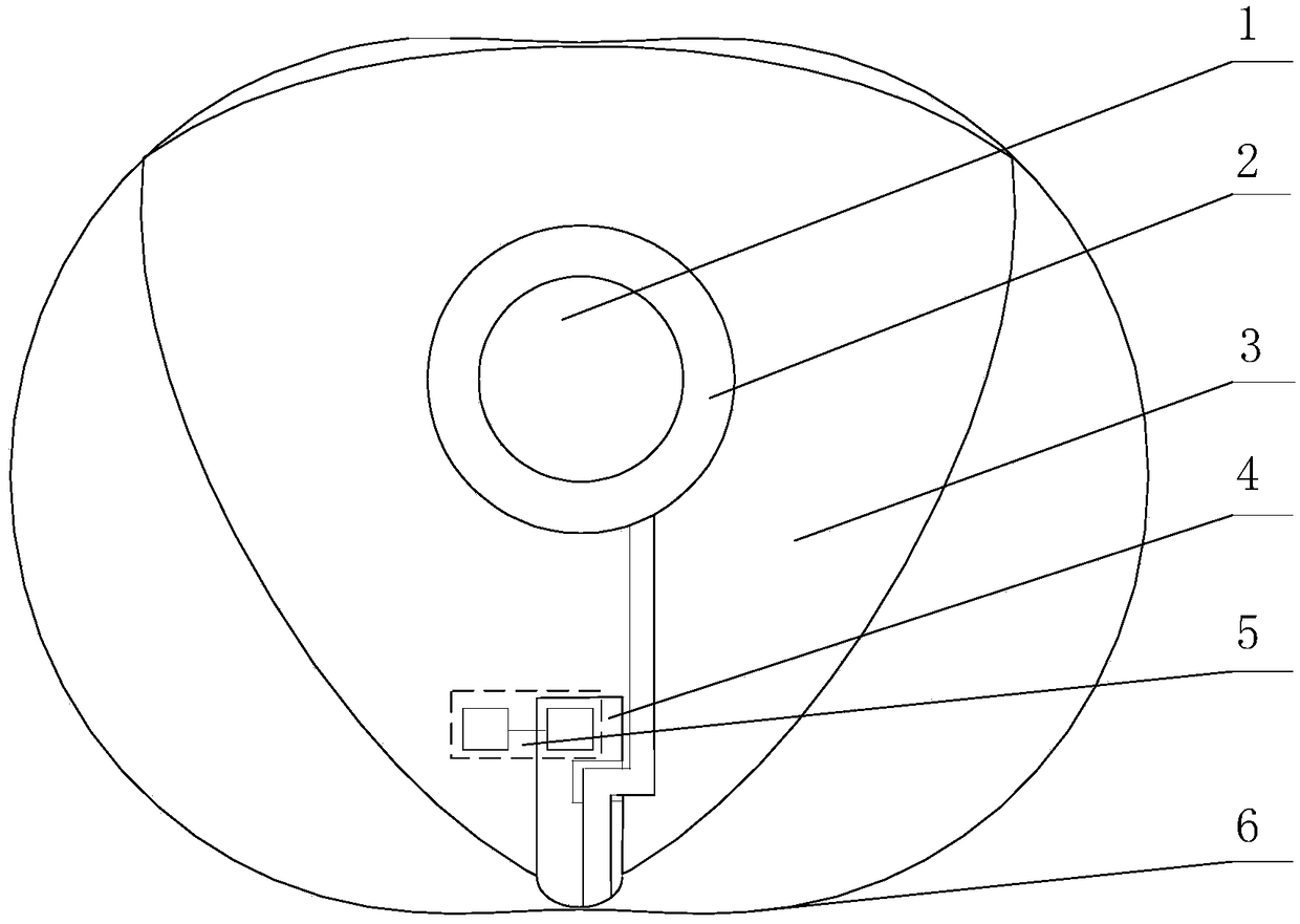
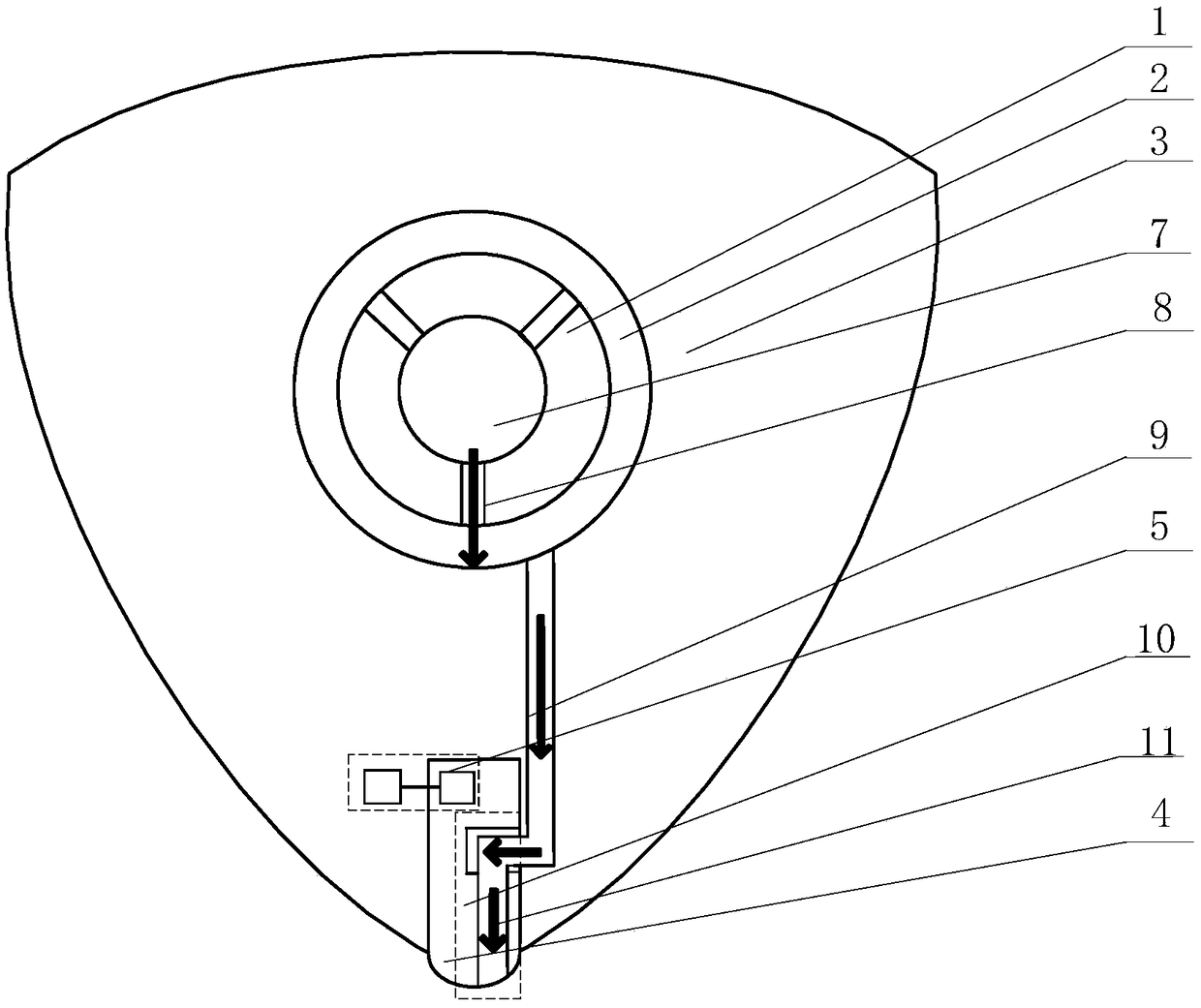
[0023] A lubrication system for a rotary engine disclosed in this embodiment includes a crankshaft 1, a bearing 2, a rotor 3, a sealing plate 4 and a supporting electronic control unit assembly 5 for controlling oil supply.

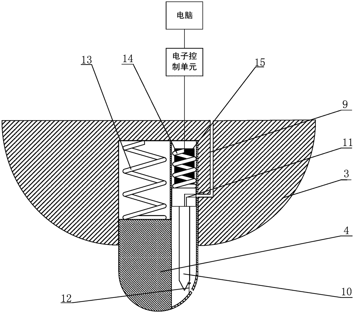
[0024] The crankshaft is processed with an eccentric shaft center oil passage 7 and an eccentric radial oil passage 8. The top ends of the rotors 3 are respectively processed with sealing sheet installation grooves. The inner side of the rotor is radially processed with an oil channel communicating with the crankshaft. The sealing sheet 4 includes a sealing sheet base, a slider oil needle integral part 10 , a one-way valve 12 , a first sealing elastic device 13 and a second sealing elastic device 14 , and a solenoid valve 15 . The first sealing elastic device 13 is located between the sealing plate base and the rotor 3, the second sealing elastic device 14 is located between the slider oil needle integral part 10 and the rotor 3, and the solenoid valve 1...


PUM


Abstract

The invention relates to a lubricating system for a rotor engine and belongs to the field of engines. The lubricating system comprises a crankshaft, a bearing, a rotor, a sealing piece and an electronic control unit component, the crankshaft is processed with an eccentric shaft central oil way and an eccentric shaft radial oil way, and an oil way communicated with the crankshaft is radially processed on the inner side of the rotor; the sealing piece comprises a sealing piece substrate, a slider and oil needle integrated member, a one-way valve, a second sealing elastic device, a second sealing elastic device and an electromagnetic valve; a communicating oil way for supplying lubricating oil is processed from an eccentric shaft to the radial sealing piece, and the electromagnetic valve is controlled by the electronic control unit component to realize reliable supply of the lubricating oil. By the lubricating system, reliable and effective oil supply can be realized when the rotor engine rotates, and lubricating of between the eccentric shaft and a bearing and between the sealing piece and a cylinder can be ensured respectively, so that friction wear is reduced, reliable sealing is guaranteed, service life of each of the eccentric shaft, the bearing, the sealing piece and the cylinder is prolonged, and running performance of the rotor engine is improved.

Description

technical field [0001] The invention relates to auxiliary equipment for micro-rotor engines, in particular to a lubricating system for rotor engines, which belongs to the field of engines. Background technique [0002] With the development of micro-electro-mechanical systems (MEMS) and the introduction of a variety of miniaturized military equipment concepts, the development of micro-energy systems with small volume, light weight, high energy density, and continuous operation has become the focus of attention of various countries. Compared with conventional portable power sources, micro-engines use hydrocarbons as fuels, which have much higher energy density, stable voltage, and low cost. Therefore, micro-engines will have wide application prospects in electronic devices in various industries such as industry, agriculture, environmental protection, medical and health care, etc., and can also directly provide power for micro-machines such as micro-cars, micro-planes, and micr...

Claims


Application Information

Patent Timeline
Patent Type & Authority Patents(China)
IPC IPC(8): F01M1/06F01M1/16F01M1/14
CPCF01M1/06F01M1/14F01M1/16F01M2001/062F01M2250/64
Inventor 刘金祥俞睿张岩
Owner BEIJING INSTITUTE OF TECHNOLOGYGY
Why Eureka
Try Eureka