
Direct resistance heating equipment applicable to heat treatment of slab metal specimen

A strip-shaped metal and resistance heating technology, applied to heat treatment equipment, heat treatment furnaces, furnaces, etc., can solve the problems that the annealing process cannot be carried out, the surface reaction is difficult to control accurately, and the adjustment of process parameters is not flexible, so as to ensure the sample preparation requirements, excellent temperature control accuracy and repeatability, and the effect of saving experimental time

Inactive Publication Date: 2014-08-06
SOUTHEAST UNIV
View PDF3 Cites 13 Cited by
  • Summary
  • Abstract
  • Description
  • Claims
  • Application Information

AI Technical Summary

Problems solved by technology

Ordinary heat treatment furnaces (such as resistance furnaces, salt bath furnaces, etc.) are one of the most important equipment for annealing experiments in my country's iron and steel enterprises. Quenching can not meet the complex and precise cooling control requirements; while the thermal cycle process control of the thermal simulation testing machine is better, the disadvantage is that the sample is small, and subsequent stretching and deep drawing experiments cannot be carried out. Another disadvantage is that the annealing process cannot be carried out. Research on surface reaction; while the continuous annealing simulation device requires coiled raw materials, high experimental cost, long cycle, and inflexible adjustment of process parameters

Method used


Image

  • Direct resistance heating equipment applicable to heat treatment of slab metal specimen
  • Direct resistance heating equipment applicable to heat treatment of slab metal specimen
  • Direct resistance heating equipment applicable to heat treatment of slab metal specimen

Examples


Embodiment Construction

[0036] The present invention will be further described below in conjunction with the accompanying drawings.

[0037] The direct resistance heating equipment suitable for the heat treatment of strip-shaped metal samples includes a heat preservation shell 1 , a main body 2 arranged in the heat preservation shell 1 , and a control device 3 .

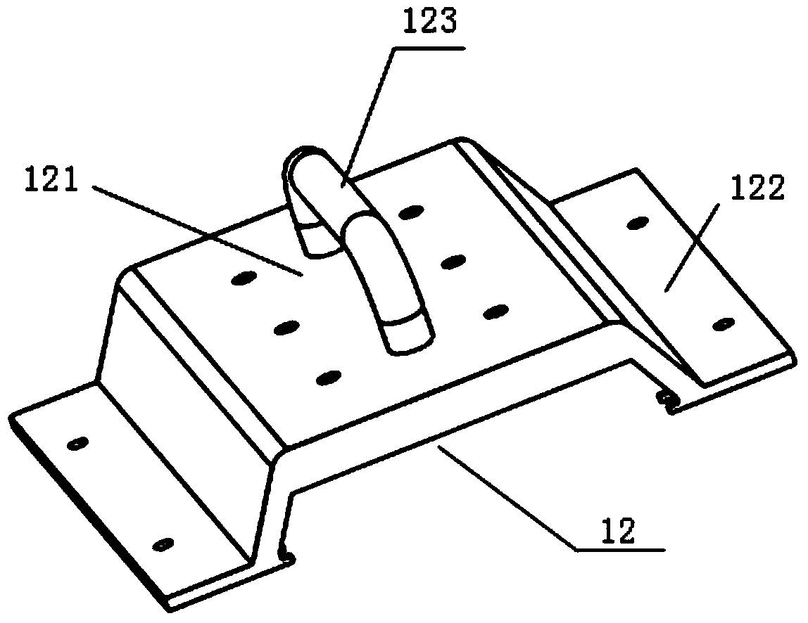
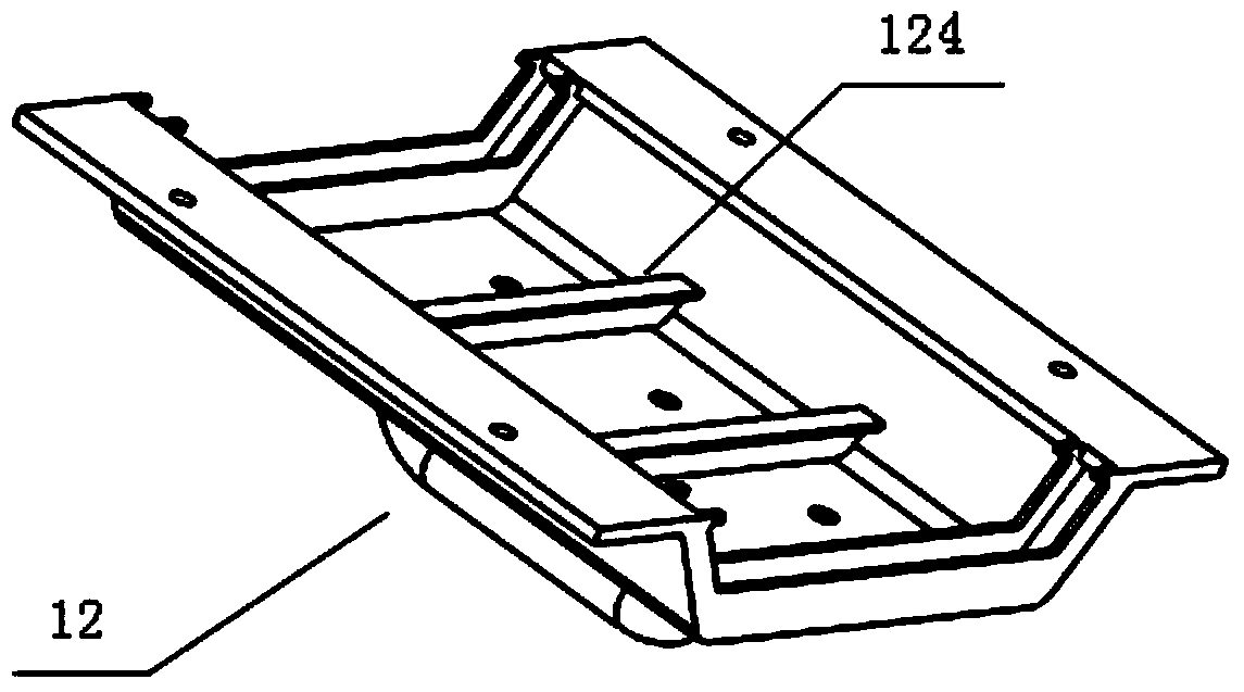
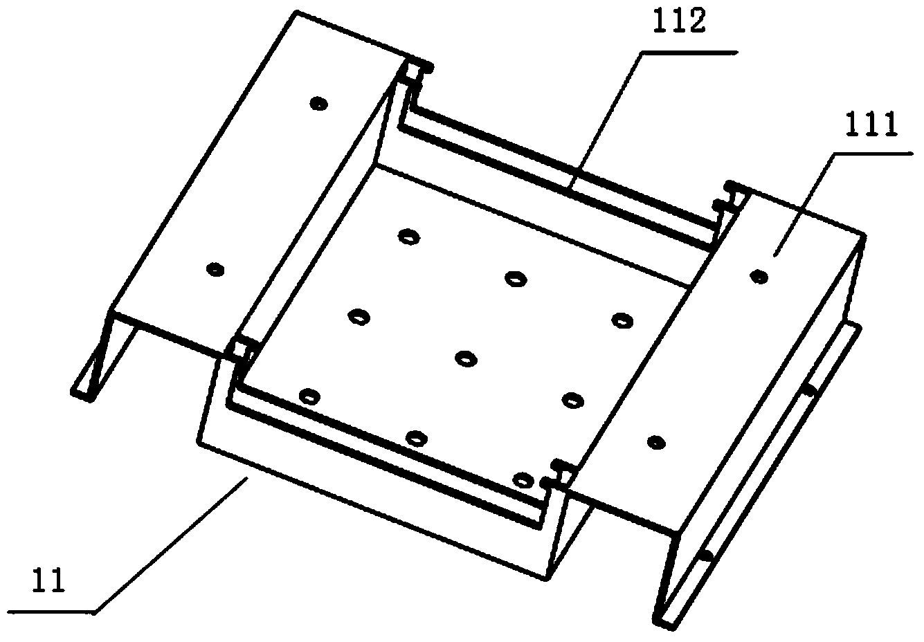
[0038] The thermal insulation shell 1, see Figure 1-3 , including a box body 11, an upper cover 12, and a high-temperature heat-resistant heat-insulating coating provided in the housing 11 and the upper cover 12, the box body 11 includes a main box body 111 and box end ribs arranged in parallel in the main box body 111 Plate 112; the upper cover 12 includes a cover top plate 121, a bead plate 122 arranged on the opposite side of the cover top plate 121, a handle 123 located at the top of the cover top plate 121 and a cover rib plate 124 located at the bottom of the cover top plate.

[0039] The subject 2, see Figure 4 , comprising a bot...


PUM


Abstract

The invention provides direct resistance heating equipment applicable to heat treatment of a slab metal specimen. The direct resistance heating equipment applicable to heat treatment of the slab metal specimen comprises an insulation shell, a main body arranged inside the insulation shell and a control device, wherein the main body comprises a bottom plate, a fixed heating electrode fixed on the bottom plate, a sliding heating electrode, a sliding device fixed on the bottom plate and a tension device, wherein the sliding heating electrode is fixed on the sliding deice; the tension device is connected with the bottom of the sliding heating electrode; the control device comprises a transformer, a thermocouple, a data collection device, a computer control system, a gear selection module, a thyristor controller and a thyristor; the thermocouple, the data collection device, the computer control system, the gear selection module, the thyristor controller and the thyristor are sequentially connected; the thyristor is connected with a primary side of the transformer; and the secondary side of the transformer is respectively connected with the fixed heating electrode and the sliding heating electrode. The equipment supports a large specimen which is to be subjected to heat treatment, can effectively prevent deformation of a conductive specimen and has excellent temperature control accuracy, repeatability and heat preservation temperature accuracy and high in efficiency.

Description

technical field [0001] The invention belongs to the field of iron and steel production equipment, in particular to a direct resistance heating equipment suitable for heat treatment of strip-shaped metal samples. Background technique [0002] The temperature control of heat treatment experimental equipment in my country's iron and steel enterprises is not accurate, and generally only can be used for air cooling, furnace cooling and water quenching, which cannot meet the complex and precise cooling control requirements. Annealing is a heat treatment process for metal materials and non-metal materials, which refers to slowly heating the metal to a certain temperature, keeping it for a sufficient time, and then cooling it at an appropriate speed; its purpose is to reduce hardness, improve machinability, and eliminate residual Stress, stable size, reducing deformation and crack tendency, refining grain, adjusting structure, eliminating organizational defects. It can be seen that...

Claims


Application Information

Patent Timeline
Patent Type & Authority Applications(China)
IPC IPC(8): C21D1/40C21D1/26C21D9/00
Inventor 朱鸣芳冯赛戴挺孙召亮
Owner SOUTHEAST UNIV
Learn More